Valves and electric jacks
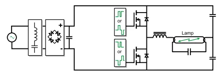
The electronic ballast is totally silent. When a discharge lamp is heating up, it supplies it with increasing voltage while maintaining a virtually constant current. At continuous rating, it regulates the voltage applied to the lamp independently of fluctuations in the mains voltage.
As the arc is powered in optimal voltage conditions, 5-10% of power is saved and the lifetime of the lamp is increased. Furthermore, the output of an electronic ballast can exceed 93%, whereas that of a magnetic device is on average only 85%. The power factor is high (> 0.9).
An electronic ballast does however have some constraints with regard to the layout used , since a diode bridge combined with capacitors leads to a power surge when the device is switched on. In operation, the absorbed current is high in third harmonic , resulting in a poor power factor of around 55%.
The third harmonic overloads in the neutral conductor. For more information, see Cahier Technique 202: The singularities of the third harmonic.
Electronic ballasts usually have capacitors between the power conductors and the earth. These anti-interference capacitors induce a constant leakage current of about 0.5-1mA per ballast.
This limits the number of ballasts that can be powered when a residual current device (RCD) is installed (see the Cahier Technique 114 Residual current device in LV).
Electronic ballast schematics
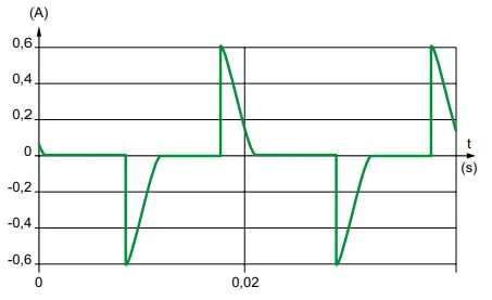
Current waveform of an electronic ballast
Forward
To complete the view of industrial loads that can be linked to automation systems, we should include a brief description of some commonly used devices: electrically-controlled screw jacks and valves.
Processes require loads to be positioned and moved. This function is ensured by pneumatic and hydraulic screw jacks but can also be controlled by electromechanical ones. These can be built into motor starter units or linked to regulating devices for, e.g. positioning control. The following pages give short description of these positioning devices.
There is a very large market in valves to control fluid flow. These are used to:
- arrest fluid flow (stop valves),
- change the fluid circuit (3-channel valves),
- blend products (mixer valves),
- control flow (regulation valves).
Fluids can be liquids or gases (ventilation or chemical industry)
Electric scewjacks
Linearly driven applications require heavy-duty electric screwjacks that are powerful, fast, long-lived and reliable. Manufacturers offer wide ranges of electric screwjacks for practically all requirements.
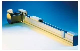
Structure of an electric screw jack
Electric screw jacks comprise a control shaft or driving member, a guide unit and an electric motor.
The photo shows an electric screw jack for linear movement.
The movement of the driving member can be linear, for travel, or rotational.
For linear movement, a screw nut system makes the driving member travel in a line.
Two of the most common systems are the ball screw and the acme screw. The acme screw is made of rolled steel and the nut is made of plastic.
Electric screw jacks
This is a fairly cost-effective design with useful properties: plastic and metal can work together well without catching.
The acme screw works quietly, so it is suitable for offices, hospitals, etc.
Another of its assets is its high friction coefficient. This design is particularly well suited to screw jacks used in applications where they must be self-locking, i.e. with no recoil against the mass of the load. For instance, when a screw jack is used to adjust the height of a table, one with an acme screw enables the table to withstand heavy loads without altering its vertical position. This means that no brake or other locking mechanism is required to maintain the load in place when it is idle.
The ball screw system is used for high performance purposes.
The ball screws in the screw jack are made of steel and have a row of ball bearings in a closed system between the nut and the screw.
This design gives a very low friction coefficient between the nut and the screw due to the rolling contact between the ball bearings, nut and tracks.
Wear is low compared to an acme screw, so the ball screw has a lifetime 10 times longer in identical operating conditions. This lifetime also implies that a ball screw can withstand heavy loads and long operating cycles.
Its low friction coefficient makes the ball screw especially efficient because it does not overheat.
The ball screw is therefore highly suited for situations requiring lengthy operation at high speed.
A screw jack with a ball screw system has very little play, so its precision is significantly better in applications where position and precision are crucial.
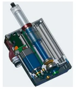
High performance electric screw jack
Product family
Electric screw jacks can be made in many different shapes and sizes to fit easily into machines. Manufacturers also offer control units to make it easier to operate them.
The photo gives a view of some products offered by one manufacturer (SKF).
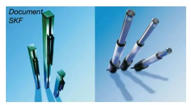
Electrical screw jacks from SKF
Selection guide
Choosing the right electric screw jack often requires detailed knowledge of the application and some calculation.
However, manufacturers’ catalogues can help in making the initial choice of screw jacks meeting the basic criteria such as load and speed.
Screw jack drives and parts
Drives offered by manufacturers. Electric screw jacks can be driven by:
- direct current motors,
- asynchronous alternating motors,
- brushless synchronous motors,
- stepper motors.
Direct current motors are usually low voltage (12 or 24 volts) for average forces (approx. 4000N) and medium performance (approx. 50mm/s). These screw jacks are used on mobile standalone battery-operated devices. An asynchronous motor drive considerably increases performance up to 50,000N and 80mm/s. These screw jacks are mostly fitted to immobile machines. Brushless drives are used for high dynamic performance (approx. 750mm/s) for forces up to about 30,000N. Stepper motor drives are used for precision positioning of the load without recoil.
Parts and variants
• Built-in controller
Some electric screw jacks have a built-in control device. This is especially the case in some types of screw jack with a brushless motor drive. These include a speed controller which can be connected to the automation system by a field bus.
• Potentiometer
The potentiometer is a movement sensor. This device is used to ascertain the position of a moving part and align it with precision.
• Thermal protection device
This protects drives and control units from overheating.
• Encoder
This is a sensor which, when it is connected to a control unit, is used to give the position of the screw jack.
• Stress limiters
Some types of screw jack are fitted with a mechanical safety device similar to a friction clutch to protect the motor and the reduction unit from damage.
• Limit switches
These are switches which limit movement in a given direction in mechanical devices by opening and closing an electrical contact. Limit switches comes in all shapes and sizes and can be fitted on the inside or outside of the screw jack.
These safety devices are part of the control system and it is important to be aware of them when using screw jacks in an automation system or any other system.
• Mechanical jamming control
This safety device makes the screw jack to stop in case of an excessive resisting force. It is provided to protect persons from injuries.
• Electrical jamming control
This is a safety option on some electric screw jacks. It cuts the power to the motor when external stress is applied in the opposite direction to screw jack movement.
Valves
Valve operating systems do not enter into the scope of this guide. That said, as valves can be part of industrial control systems such as regulation loops or speed controllers, it is useful to have some idea of their structure and what happens when they work.
Valve structure
A valve consists of a body and a throttle which presses against a seat. Fluid movement is controlled by an operating rod. This rod is actuated by electric or pneumatic devices.
Many valves are pneumatically controlled, others are electrically controlled (solenoid valves).
There are many different valve designs (butterfly, spherical, diaphragm, etc.) for different types of use, fluid and progression rates (output in relation to the position of the throttle or the control signal in regulation valves).
The throttle usually has a specific shape to prevent or mitigate any unwanted effects such as water hammer or cavitation.
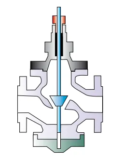
Cross view of a valve
• Water hammer
This can occur in hydraulic pipes when the valve is closed. The flow through the pipe is suddenly stopped and causes this phenomenon known as water hammer.
As an example , here is a description of a pumping station feeding a reservoir above the feed pump.
When the emptying valve is closed, the water drained from the reservoir via the pump below the fluid column tends to pursue its movement while there is no more output from the pump
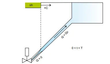
Water hammer (start)
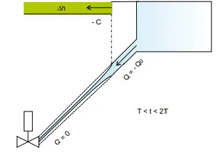
Water hammer
This movement causes elastic deformation of the pipe which contracts at a point near the valve.
This phenomenon makes the mass of fluid temporarily available and maintains it in movement.
Depression occurs and spreads throughout the pipe at the speed of elastic waves C until the entire pipe is affected by it, i.e. after a time T=L/c, where L is the length of the pipe between the valve and the outlet.
The result is that the pressure where the pipe goes into the reservoir is lower than the pressure in the reservoir and causes backflow. The wave spreads from the reservoir to the pumping station and reaches the valve throttle after a time 2T from the start of the phenomenon.
The fluid column continues its descent and hits the closed valve again, causing the pipe to swell and reversing the movement of the fluid.
Water hammer would occur indefinitely if the effects of load loss, depression and overpressure are not gradually dampened.
To overcome this potentially destructive phenomenon, valve closing can be controlled by a system based on a slow closing law to keep overpressure and depression within reasonable limits.
Another procedure involves gradually slackening the speed of the feed pump to enable the valve to close the pipe.
In the case of pumps running at constant speed, the most suitable device is a soft start device such as Altistart by Telemecanique or Altivar for speed-controlled pumps.
• Cavitation
Closing a valve results in restricting the section available for fluid flow. Applying the Bernoulli theorem, restricting the flow section left by the valve accelerates the flow and lowers static pressure at that point.
The amount of static pressure drop depends on:
- the internal geometry of the valve,
- the amount of static pressure downstream of the valve.
The pressure when the valve is open is shown on (C curve 1).
Flow is restricted at the point of the closing valve throttle, causing a drop-in pressure and accelerated flow (Venturi effect);
When the throttle closes, the Venturi effect increases and curve 1 is gradually deformed (C curve 2).
When the static pressure in the fluid vein reaches the value of the vapour tension at the flow temperature, vapour bubbles form in the immediate vicinity of the restricted flow. When the static pressure rises again downstream of the valve (pressure P2), the vapour bubbles condense and implose. Cavitation has the following undesirable effects:
- unacceptably loud noise, rather like pebbles rattling in the pipes,
- vibrations at high frequencies which loosen the valve nuts and other parts,
- rapid destruction of the throttle, seat and body by removal of metal particles. Surfaces subject to cavitation are grainy,
- the flow through the valve is related to valve opening.
Regulation valves are often required to operate for a long time in conditions where cavitation can occur, and their lifetime will be seriously affected by it.
Ways of limiting or preventing cavitation do not enter into the scope of this guide.
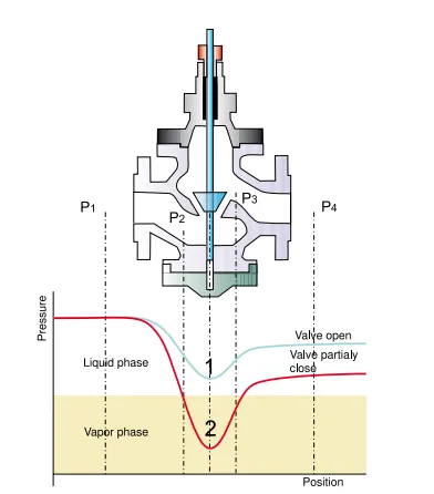
Cavitation phenomenul