Fuzzy Logic Control of Switched Reluctance Motor Drives
The switched reluctance machines could be claimed to have a pivotal role in the changes in electrical machines technology since the mid-1960s. Switched reluctance motor (SRM) torque is generated by rotor moving where the inductance of each phase is maximized. The simple structure is the main attractive feature as there is no winding or permanent magnet. Therefore, the manufacturing cost is lower than other electrical machines. SRMs have a wide range of applications in industry, such as hybrid vehicles, wheelchairs, aircrafts, starter/generator systems, washing machines, and other industry and home applications [1, 2].
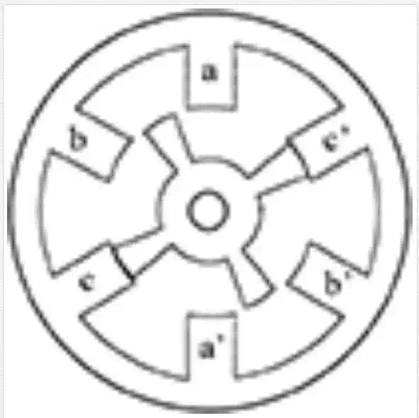
The SRM windings are excited by an external DC supply and current is injected only into one phase. A simple SRM with three stator phases is shown in Figure 1. It is clear that the stator has six poles and the rotor possesses four poles. In the SRM, DC circuit supplies are simpler in construction of power switches than those of other motor drives. Therefore, many manufacturers have very high intends for applying SRMs in home electrical motors. Also, high torque at low speeds can make SRM suitable for direct use without gearbox. However, in comparison with high performance motors, SRM suffers from a high-level acoustical noise and mechanical vibration. When one phase is excited, the rotor rotates until two of its poles are aligned with two stator poles of the excited phase and torque is generated by increasing the inductance while reluctance of the magnetic circuit decreases.
The stator poles and salient rotor provide an un-uniform air gap, which leads to nonlinear behavior of electromagnetic equations in SRM [3]. As we know, vehicles need initial acceleration and gradability with minimum power rating. Rahman et al. have investigated the capabilities of the SRM for the electric vehicle (EV) and hybrid EV applications. These investigations have been carried out in two stages. First stage involves the machine design and the finite element analysis of static characteristic and in second stage, the finite element field solution have been used in the development of a nonlinear model. Experimental results have demonstrated the improvement of PF at a high-speed operation [4]. A large number of methods have been also introduced to accomplish position sensor-less operation of the SRM during the last 15 years. Mese and Torrey have presented a new approach to the sensor-less control of the SRM. In this method, an artificial neural network (ANN) acts on the measurement of the phase flux linkages and phase currents. The investigations conducted throughout this research have shown that a properly trained and utilized ANN is capable of estimating the rotor position of SRM within acceptable accuracy limits. The method deserves consideration as a candidate for integration into practical SRM drive systems [5]. Most modern high-performance AC drives utilize synchronous frame current regulators, which see a pure DC current command in steady state. Schulz et al. have introduced a designed methodology for digital proportional–integral current regulators that may be used for the highly nonlinear SRM control. In this procedure, the main goal was to focus on the development of a fully digital implementation of the inner current control loop for high-performance SRM drives operating with high saturation. Simulation and experimental results have demonstrated the excellent performance over the entire operating regime [6]. Rotor position sensors, such as shaft encoders and Hall effect sensors, have been applied in SRM drives to determine the rotor position. These sensors increase drive cost and decrease reliability of the SRM drive in industrial applications. Gao et al. proposed a sensor-less control scheme for SRM drive at low speed. In this study, incremental inductance of each active phase is estimated by using the terminal measurement of this phase. Simulation and experimental results have shown that errors between estimated position and actual position (measurement position) are less than one mechanical degree [7]. Husain and Hossain have presented the modeling, simulation and control aspects of four-quadrant SRM drives.
A complex model has been described for the physical motor simulation to incorporate the important dynamics of the SRM. The results obtained from the final simulation model are extremely close to the experiments. Such a model could be reliably used for performance evaluations and future developments [8]. A sensor-less drive that decreases cost and increases reliability, which extracts rotor position information indirectly from electric signals of motor terminals, is highly desirable. A sliding mode observer, with its advantages of inherent robustness parameters of uncertainly, computational simplicity, and high stability, provides a powerful approach to implement sensor-less schemes. Divandari et al. have presented the estimated the rotor position and speed of SRM drive based on hybrid observer (HO). The HO has provided online estimates of the rotor position and speed for a wide speed range using the current sliding mode observer (CSMO) and flux linkage sliding mode observer (FSMO). In addition, a fuzzy logic current compensator (FLCC) for reducing torque ripple is presented. Simulation results have shown that proposed SRM drive decreases estimation errors and torque ripple, effectively. The method has good performance in a wide speed range [9, 10]. One of the main problems in sensor-less SRM drive is position sensing at startup. Yan-Tai et al. [11] proposed a method for position sensing at startup using quadratic polynomial regression. In this method, without using magnetic specifications, position estimation at startup can be done by a microcontroller. The magnetic flux in the SRM passes across the air gap in an approximate radial direction generating radial forces on the stator and rotor, resulting in magnetic noise and vibrations. Unbalanced radial forces acting on a rotor shaft are undesirable as they cause motor vibrations. Lin and Yang proposed a new excitation approach for the torque and radial force control of a 12/8 poles SRM. In this method, the SRM drive can generate simultaneously the modified shaft radial force and rated torque.
The experimental results verified that the SRM produced smoother torque ripples when the proposed commutation scheme was used [12]. Harmonics magnitude of the radial force has basically role in acoustic noise generation. Takiguchi et al. [13] proposed a new method for elimination of second and third harmonics. They compared experiment results with finite-element method. Also, for acoustic noise reduction, Hyong-Yeol et al. [14] introduced an applicable approach by new rotor and stator design. In this approach, laminations of rotor and stator have similar skew angel and radial force can be decreased significantly by changing air gap uniform. As we know, because of SRM dynamical nonlinearities, its control is complex. Hajatipour and Farrokhi have introduced an adaptive intelligent control based on the Lyapunov stability theory to control the speed of SR motors with good accuracies and performances. The proposed controller is composed of a speed controller and a torque controller. Moreover, the torque ripple reduction was achieved by employing a neural network for torque estimation. The simulation results showed a good performance of the proposed controller in speed controlling and torque ripple reduction [15]. Most observers are static and once their gains have been determined. As we know, most observers are based model and uncertain in parameters will increase estimation errors. Therefore, online gain regulation can improve deficiency of based model observers. A new generation of observers named dynamic observers (DO) described by Divandari et al. [16]. Dynamic observers can be used in tracking and drive systems. Also, main problem of SRM is high torque ripple, and this problem will be solved by optimization of motor design and improvement of drive performance. We suppose a SRM is already built; therefore, torque ripple can be minimized by the optimization of the current waveform in the SRM drive. Divandari et al. have proposed a new simple procedure for minimizing the torque ripple via fuzzy logic control of the SRM. Simulation results have demonstrated that proposed drive estimates rotor speed with high accuracy for a wide speed range. Also, the fuzzy logic current compensator optimizes the torque ripple and decreases estimation error.
In this chapter, to define a SRM drive, simulation, and investigations of the SRM behavior such as torque ripple, rotor position estimation, and acoustic noise, we present a nonlinear model of the SRM by using experimentally measured characteristics. After modeling, with current profile optimization via fuzzy logic control (FLC), the torque ripple is minimized. Acoustic noise sources in the SRM depend on torque ripple and radial force. Therefore, we discuss about radial force and important parameters in radial force and torque ripple, together. Calculations of radial force with two methods are expressed as well. By using FLC, the torque ripple and radial force are optimized. Also, in this chapter, the study of a low-cost, sensor-less-based, and speed-controlled SRM drive system is considered. A hybrid algorithm (HA) with CSMO and flux sliding mode observer (FSMO) is developed to estimate rotor position and speed of the SRM. The observer gains will be updated separately online at a wide speed range with band of estimated errors. Also, by means of indirect speed estimation, we propose torque compensation by current profile.In the following paragraphs, this chapter presents an intelligent solution for SRM drives.
Non-linear model of SRM
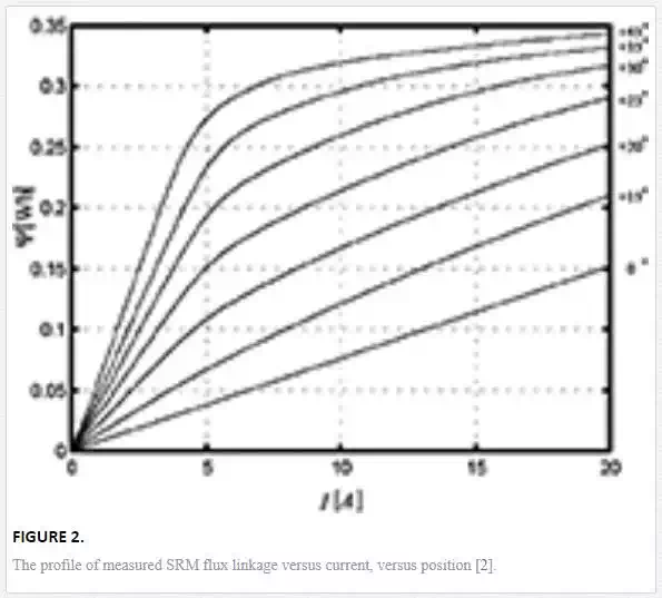
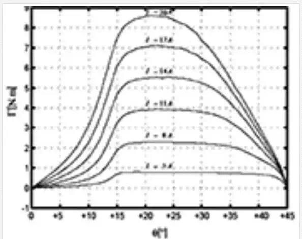
To study the characteristics of SRM drive system such as current profile, torque ripple, rotor estimation, radial force, and acoustic noise, we should present a nonlinear model of SRM. Also, for SRM differential equations, it is required to study dynamic characteristics consisting of flux linkage and torque. The measured flux linkage data and torque data applied in this chapter for each phase of SRM are shown in Figures 2 and 3 [16].
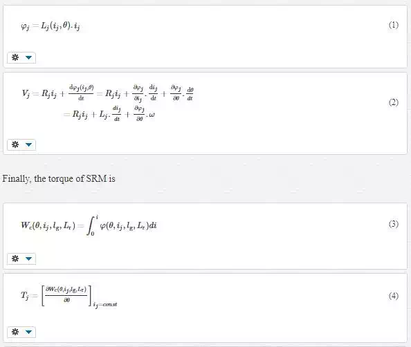
The torque and flux depend on position and current. The flux and voltage for each phase of SRM can be expressed as:
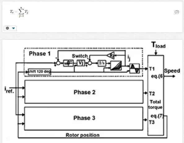
The mathematical motion of the motor by the action of electromagnetic torque and load torque is
|
(6) |
The equation of rotation is
|
(7) |
According to differential equations and measured data, block diagram of nonlinear model of three-phase SRM is shown in Figure 4.
Torque Ripple minimization with FLCC
As we know, the main disadvantage of SRM is a high level of torque ripple. One of the methods to decrease the torque ripples is the deformation of the current profile [17]. This chapter presents a new simple technique for minimizing the torque ripple via FLC. This technique is based on the transfusion of additional current in each phase by using FLCC [10].
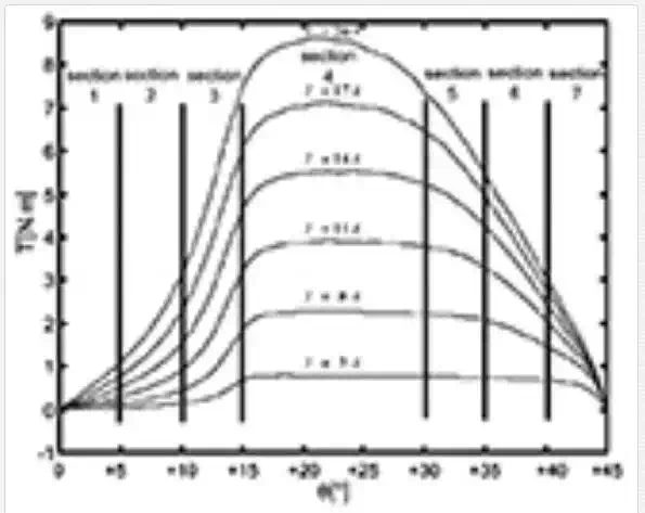
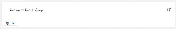
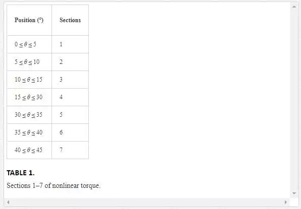
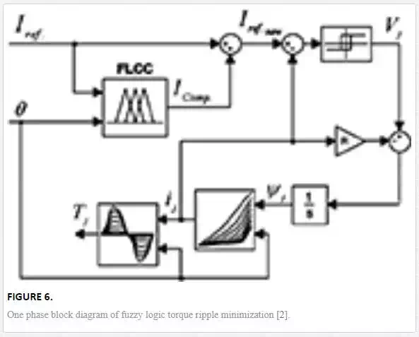
Furthermore, torque ripple is one of the main acoustic noise sources in SRM drive. Therefore, torque ripple minimization techniques reduce mechanical vibrations on the bearing and increase estimation errors. In this method, nonlinear torque curves are divided into seven sections (1–7). These sections are shown in Figure 5. Each section is 5° and in each 5°, the nonlinear torque behavior can be considered linear. SRM torque in section 5 is nearly flat, but in other sections, negative torque slop will be compensated by using FLCC. The 1–7 sections of torque curves have been listed in Table 1. Also, the one-phase block diagram of fuzzy logic torque ripple minimization is illustrated in Figure 6. Fuzzy rules are defined for a wide speed range (near zero speeds up to rated speed). FLCC acts on the reference current when torque curve is 1–3 and 5–7 sections. According to current compensation, new reference current is
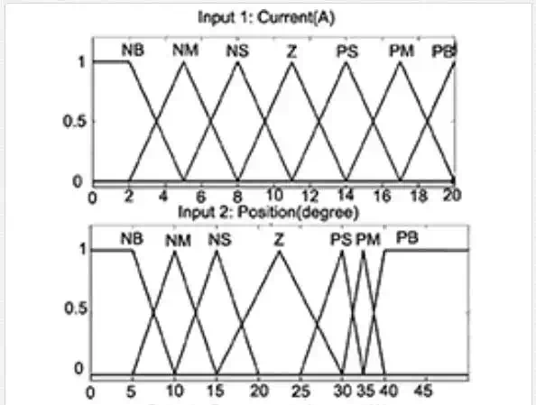
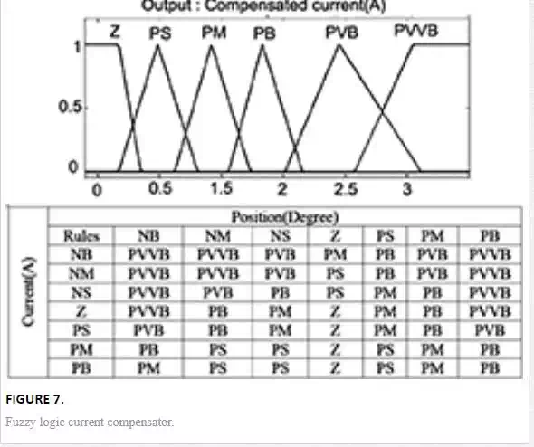
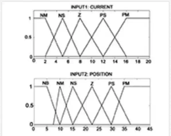
As we know, fuzzy membership function arrangements and fuzzy rules determination have a main role in designing FLCC for torque ripple minimization. In this technique, the current and rotor position with seven membership functions as inputs and the compensated current with six membership functions as output are determined. In the sections of A, B and F, G which torque decrease with big negative slope, fuzzy rules set up on PVB or PVVB but in the C and E sections which torque reduces with slow negative slope, fuzzy rules set up on PB and PVB. Also, at high speeds, fuzzy rules are moderated to PB because high current peaks in motor current will cause damage to power switches and the SRM. Figure 7 shows the input and output membership functions as well as the fuzzy rules. Input 1 (current) is defined 0–20 A, input 2 (position) 0–45 degree, and output (compensated current) 0–3 A [index 1].
Acoustic noise reduction
Mechanical vibration and the acoustic noise in SRMs cause that they could not commercially yet competitive with other electrical machine drives. Noise sources recognition and elimination or reduction of noise in electrical machine drives can be dated since the 1940s when new materials were presented to improve electrical machines designs [17]. As we know, SRM radial force and torque ripple are the important sources of acoustic noise generation in SRM drives. When stator winding of each phase is energized by DC external supply, a magnetic flux will cross from air gap and an approximate radial force excites diverse mode shapes. Moreover, energizing stator winding in the SRM with a DC voltage generates lateral force, tangential force, and torque. The current in the stator windings could generate a magnetic flux in stator winding that would emit acoustic noise [2].
Radial force is relevant to many parameters such as air gap length, position, rotor length, and rotor radius. Also, radial force depends on current square and turns number of stator windings, and sound power is relevant to radial force square. In the last decade, researches illustrate that most of the studies focus on the torque ripple minimization while stator and rotor shape design and radial magnetic force have principle rule at acoustic noise of the SRM. In this procedure, torque ripple will be minimized and the maximum radial force decreases while we try to maintain maximum torque by the current profile deformation via FLC. This technique is based on transfusion of additional current by using FLC.
CALCULATION OF SRM RADIAL FORCE
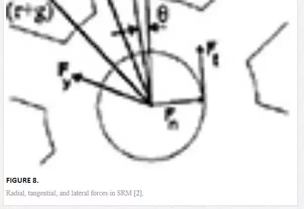
As it was mentioned in previous sections, the radial force and acoustic noise are relevant to many SRM parameters. Magnetic specifications, machine design, and material type are effective in the radial force calculation. For more study, we should first analyze the equations of radial, tangential, and lateral forces. Figure 8 shows radial, tangential, and lateral forces in the SRM. The flux density in the SRM air gap between stator and rotor is given as
|
Bg(θ,ij,lg,Lr)=φLr.r.θ=μ0.Hg=μ0.Nph.ijlgNph=lgμ0.Lr.r.ij.φθBg(θ,ij,lg,Lr)=φLr.r.θ=μ0.Hg=μ0.Nph.ijlgNph=lgμ0.Lr.r.ij.φθ |
(9) |
where Nph is the turns number for each phase, r is the outer rotor radius, Hg is the magnetic field strength, and μ0 is the air permeability.
The electrical energy (dWe) is expressed by

The stored energy in the magnetic field (Ws) is
|
Ws=lg.Lr.r.θ2μ0.B2g(θ,ij,lg,Lr)=lg2μ0.Lr.r.φ2θWs=lg.Lr.r.θ2μ0.B2g(θ,ij,lg,Lr)=lg2μ0.Lr.r.φ2θ |
(11) |
where lg.Lr is the air gap specifications and constant value. The energy equation is
|
(12) |
wheredWm is the mechanical energy and dWs is the field energy. In this chapter, we propose two procedures for tangential, radial, and lateral force calculations. In the first procedure, of the tangential force calculations obtained from Eq. (12) as
|
dWs=−lg2μ0.Lr.r.φ2θ2dθ+lgμ0.Lr.r.φθdφdWs=−lg2μ0.Lr.r.φ2θ2dθ+lgμ0.Lr.r.φθdφ |
(13) |
By substituting Eqs. (10) and (13) in Eq. (12), the mechanical energy is calculated as
|
(14) |
Moreover, electromagnetic torque is
|
Te=dWmdθ=lg2μ0.Lr.r.φ2θ2=lg.r.Lr2μ0.B2g(θ,ij,lg,Lr)Te=dWmdθ=lg2μ0.Lr.r.φ2θ2=lg.r.Lr2μ0.B2g(θ,ij,lg,Lr) |
(15) |
Also, the tangential force is obtained by dividing tangential torque by the radius of the rotor pole, yielding
|
Ft=Ter=lg.Lr2μ0.B2g(θ,ij,lg,Lr)Ft=Ter=lg.Lr2μ0.B2g(θ,ij,lg,Lr) |
(16) |
and the radial force is given by
|
Fn=dWmdlg=12μ0.r.Lr.φ2θ=r.Lr.θ2μ0.B2g(θ,ij,lg,Lr)Fn=dWmdlg=12μ0.r.Lr.φ2θ=r.Lr.θ2μ0.B2g(θ,ij,lg,Lr) |
(17) |
Similarity, the lateral force can be derived as
|
(18) |
The ratio of the radial force to the tangential force from Eqs. (17) and (18) becomes
|
(19) |
and rotor angle is given as
|
(20) |
where Ps is number of stator poles and Pr is the number of rotor poles. In the next procedure, we should apply Eq. (3) and flux equation. Flux equation is given as
|
φ=Bg(θ,ij,lg,Lr).A=μ0.Lr.r.θ.N2ph2lg.ij=μ0.Lr.r.θ.N2phlg.ijφ=Bg(θ,ij,lg,Lr).A=μ0.Lr.r.θ.N2ph2lg.ij=μ0.Lr.r.θ.N2phlg.ij |
(21) |
Substituting Eq. (21) in Eq. (3), co-energy is obtained as
|
Wc(θ,ij,lg,Lr)==μ0.Lr.r.θ.N2ph2lg.ij2Wc(θ,ij,lg,Lr)==μ0.Lr.r.θ.N2ph2lg.ij2 |
(22) |
Finally, torque and tangential, radial and lateral forces are obtained as
|
Te=∂Wc(θ,ij,lg,Lr)∂θ=lg2μ0.Lr.r.φ2θ2Te=∂Wc(θ,ij,lg,Lr)∂θ=lg2μ0.Lr.r.φ2θ2 |
(23) |
|
(24) |
|
Fn=∂Wc(θ,ij,lg,Lr)∂lg=K.(−r.Lr.θ2μ0)Fn=∂Wc(θ,ij,lg,Lr)∂lg=K.(−r.Lr.θ2μ0) |
(25) |
|
Fy=∂Wc(θ,ij,lg,Lr)∂Lr=K.(lg.r.θ2μ0)Fy=∂Wc(θ,ij,lg,Lr)∂Lr=K.(lg.r.θ2μ0) |
(26) |
respectively, where
|
(27) |
Eqs. (23), (25), and (27) illustrate the radial force and torque. It is clear that radial force and torque are directly relevant to current square.
CALCULATION OF SRM ACOUSTIC NOISE
The acoustic noise value is relevant to circumferential perversion due to the radial force wave. The analytical presentation for the circumferential perversion can be defined as
|
Dcircum(fexc)=12.Fn(fexc).Rmm4.E.(Rmhs)3{1−(fexcfm)2}2+(δπ.fexcfm)2⎷Dcircum(fexc)=12.Fn(fexc).Rmm4.E.(Rmhs)3{1−(fexcfm)2}2+(δπ.fexcfm)2 |
(28) |
|
(29) |
where
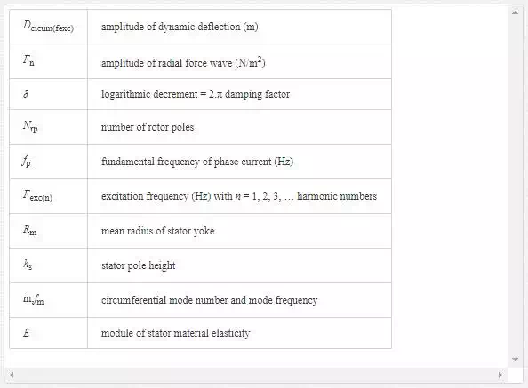
Sound power radiated by an electric machine can be expressed as
|
P=4σrelρcπ3f2excDcircumRoutlstkP=4σrelρcπ3fexc2DcircumRoutlstk |
(30) |
Where
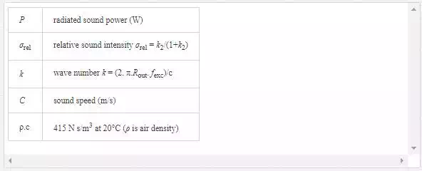
Rout, lstk outer radius and stack length of the stator (m) [2]. Depending on the threshold of human ear sensation, the reference of sound power level (Pref) is 10–12 W. Consequently, the acoustic noise power level in decibels becomes
|
(31) |
Acoustic Noise Rreduction (ANR) with FLC
In the SRM drive, radial force is dependent on
|
(32) |
Also, SRM torque is function of
|
Te∝K∝ii2Te∝K∝ii2 |
(33) |
In this procedure, we suppose that SRM has been already built. Our aim is to optimize radial force and torque ripple in the SRM drive so far as keep maximum torque using phase current waveform. Figure 9illustrates the characteristics of torque and radial force of SRM at rated current. Two sections (1 and 2) can be seen in Figure 9. In the A area not only torque decreases but also radial force increases and even will be maximized, but in the B area, torque increases and will be maximized. Also, radial force will not be maximized.


Therefore, with discussions of torque ripple minimization and fuzzy logic rules, we can keep the maximum torque and reduce radial force, and consequently, acoustic noise will be reduced.Finally, Figure 10 shows the fuzzy logic member functions for current waveform and fuzzy logic rules for acoustic noise reduction (ANR) and torque ripple minimization, respectively. Input 1 (current) is defined 0–20 A, input 2 (position) 0–45°, and output (compensated current) 0–5 A [index 1].
Estimate of position and speed of SRM
Applying a shaft encoder in electrical machine drive decreases the reliability and increases the cost of drive. Therefore, usually researchers measure electrical signals consisting of voltages and currents for position estimation. The recent well-known methods for position estimation in the SRM drives have been focused on the three methods:
1. Model-based observer.
2. Inductance-based measurement applying current fall time or rise time.
3. Inductance-based estimation applying the two separated methods: (a) demodulation and constant current and (b) constant flux used to sensor signals [17]
Researchers have proposed many methods of sensor-less SRM drives in the last decade. In these methods, estimation techniques have been applied for either rated speed or low speeds. One of these methods is sliding mode observer (SMO). SMOs have many advantages such as inherent robustness in parameters uncertainly, fast computational, but they have some disadvantages such as sensitive to model changes and selecting of SMO gains.
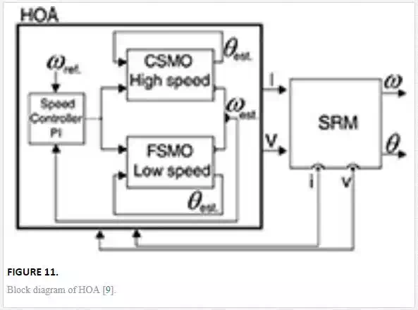
In this method, a hybrid observer algorithm (HOA) is proposed to estimate position in the SRM drive for a wide speed range. Proposed HOA consists of two SMO: CSMO and FSMO. The CSMO and FSMO gains will be regulated in high and low speed with value of estimation error, respectively [16].
The block diagram HOA is illustrated in Figure 11. HOA consists of CSMO, FSMO, and a proportional integral controller for speed control.
CURRENT SLIDING MODE OBSERVER
Proposed CSMO for sensor-less SRM drive has two strategies:
· Measuring of electrical signals (voltages and currents).
· Voltages as inputs to nonlinear model in which currents will be estimate
· Principle of CSMO operating is constructed on the current error for high speeds. Block diagram of CSMO is shown in Figure 12.
· According to the system differential equations derived from the nonlinear model of SRM, a CSMO for rotor position and speed can be defined as follows:
|
S(t)=ij−ijest.S(t)=ij−ijest. |
(34) |
|
(35) |
· Differential equations of CSMO are
|
(36) |
|
|
(37) |
· The estimation error is defined as follows:
· eθ=θest.−θ,eω=ωest.−ωeθ=θest.−θ,eω=ωest.−ω
· Consequently, by subtracting Eq. (36) from (7) and Eq. (37) from (6), we get the error dynamics:
|
(38) |
|
|
e.ω=[Te−TlJ]−[Te−TlJ]est.−αωC.Scont.e.ω=[Te−TlJ]−[Te−TlJ]est.−αωC.Scont. |
(39) |
· By appropriately choosing the two CSMO gains αϑC, αωC can make:
|
(40) |
|
|
(41) |
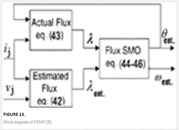
FLUX SLIDING MODE OBSERVER
· The FSMO acts on the flux linkage error for low speeds. In this SMO, voltages and currents of each phase will be measured. Figure 13 illustrates the FSMO block diagram. The flux linkage of jth phase is estimated by using the voltage and current as follows:
|
λjest.(t)=∫t0t(Vj(τ)−ij(τ).rj)dτλjest.(t)=∫t0t(Vj(τ)−ij(τ).rj)dτ |
(42) |
· where vj, ij, and rj are the voltage, current, and resistance of jth phase. An accurate but simplified flux linkage model is used to obtain the phase flux linkage and is given as follows:
· Z(ij,θ)=ij.Wj(θ)Z(ij,θ)=ij.Wj(θ)
· Wj(θ)=cos(Nr.θest.−(n−1)2πNph)Wj(θ)=cos(Nr.θest.−(n−1)2πNph)
|
(43) |
· where Nr is the number of rotor poles, and Nph is the number of phases, θest. is the estimated position, and ƛs is the saturated flux linkage consequently, flux linkage error is
|
eλ=∑j=1NphdWj(θ)dθθ=θest..(λj−λjest.)eλ=∑j=1NphdWj(θ)dθθ=θest..(λj−λjest.) |
(44) |
· and differential equations of FSMO are
|
(45) |
||
|
(46) |
||
By appropriately choosing the two FSMO gains αϑF, αωF can make:
|
(47) |
INDIRECT SPEED ESTIMATION BY TORQUE ESTIMATION
Illustrated in Figure 14 sensor-less SRM drive scheme is proposed. In this proposed method, sensor-less SRM drive is model based and torque estimator just acts based on the measured phase voltages and measured currents. Finally, in this approach, a PI controller is applied for SRM speed control [18].
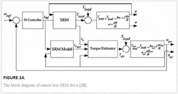
The sensor-less SRM drive is designed to estimate indirect speed and rotor position. The SRM torque is functional of phase current and rotor position. Thus, error of phase current and estimated current of the SRM plays basic role in torque estimation.Current error for each phase ekek can be defined as follows:
|
(48) |
For the purpose of current compensation, current error should be bounded. Error bound can be described as
|
(49) |
|
|
(50) |
Torque estimation algorithm is obtain as
|
if: ek<−β⇒ikcomp.=ik+α.f(ek,ė k)if: ek<−β⇒ikcomp.=ik+α.f(ek,ėk) |
(51) |
|
elsif: ek>β⇒ikcomp.=ik−α.f(ek,ė k)elsif: ek>β⇒ikcomp.=ik−α.f(ek,ėk) |
(52) |
|
(53) |
where α,β,γα,β,γ are determined using fuzzy logic.
Figure 15 illustrates the adaptive fuzzy logic of torque estimator of the kth phase. The torque of each phase using lockup table and compensated current can be calculated using Eqs. (51)–(53).
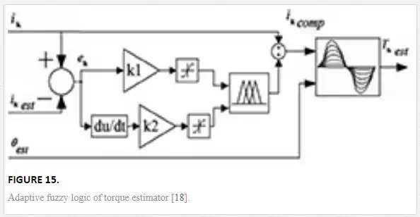
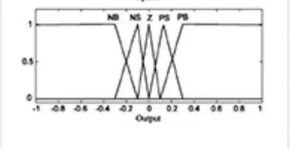
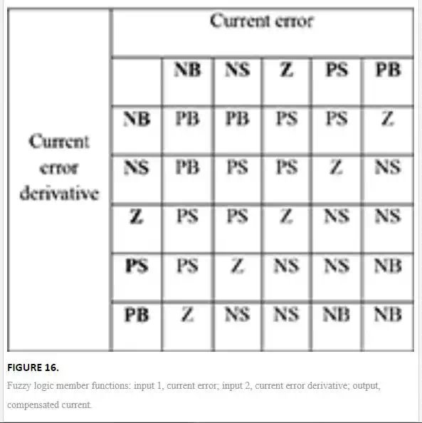
In fuzzy logic compensator, fuzzy rules act on current error (with five membership function: NB, NS, Z, PS, PB) and current error derivative (with five membership functions: NB, NS, Z, PS, PB) as inputs and compensated current (with five membership functions: NB, NS, Z, PS, PB) as output. Figure 16 shows fuzzy logic membership functions. In this section, current error −0.4 to 0.4 as ββ (input 1), current error derivative −0.3 to 0.3 as γγ (input 2), and α.f(ek,ė k)α.f(ek,ėk) −0.3 to 0.3 as output are evaluated. Also, inputs and output ranges are normalized between −1 and 1. Table 2 shows fuzzy logic rules. It is clear that arrangements of rules are symmetric and have an opposite behavior of current error and the evaluated error derivative [index 1].

|
input1: µi1(x)={0,1}input1: µi1(x)={0,1} |
(54) |
|
(55) |
|
|
(56) |
where µi1(x), µi2(x), µo(x)µi1(x), µi2(x), µo(x) are membership functions.
Simulation results
NONLINEAR MODEL SIMULATION OF SRM
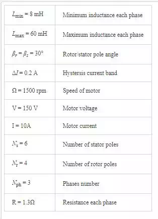
The proposed methods are simulated by MATLAB/ SIMULINK, where the parameters of SRM are listed in Table 2. In these simulations, turn-on/turn-off angles have been selected for minimizing the torque ripple and optimizing the speed estimation.

TORQUE RIPPLE MINIMIZATION
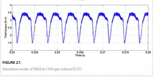
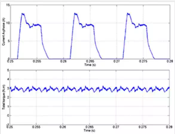
Figure 18 shows the simulation results with FLCC for ω = 1500 rpm. These results show the one phase current wave form and total torque. In Figure 18, minimum torque and maximum torque are 2.8 and 3.2 N m (ΔT = Tmax−Tmin = 0.4 N m), respectively. As it can be seen, phase current waveform is varied for torque ripple reduction.
ACOUSTIC NOISE REDUCTION
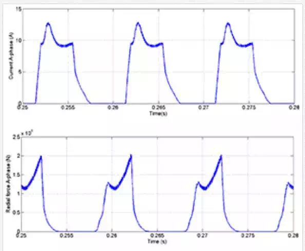
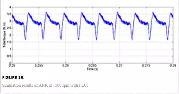
Figure 19 illustrates the simulation results ANR with FLC for ω = 1500 rpm. These results show the one phase current wave form, one phase radial force, and total torque, respectively. In Figure 19, FLC optimizes reference current by means of reduction of maximum radial force and keeping the maximum torque and torque ripple minimization. It can be observed that the maximum radial force, the maximum torque, and the torque ripple are 2 × 10⁶ N, 3.5 N m, and (ΔT = Tmax−Tmin = 0.7 N m), respectively.
ESTIMATION OF ROTOR POSITION AND SPEED WITH HO
Finally, Figure 20 illustrates the simulation results of estimation of rotor position and speed at 50, 100, 500, 1000, 1500 rpm with HO. In Figure 20, speed and estimated speed, position and estimated position, and speed estimation error waveform for a wide speed range are shown.
SPEED ESTIMATION BY TORQUE ESTIMATION
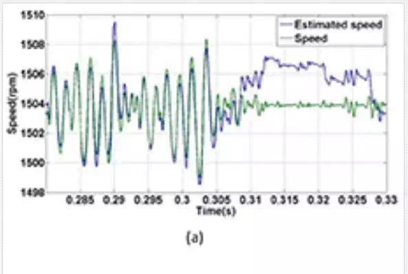
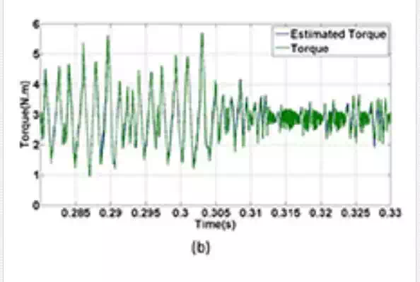
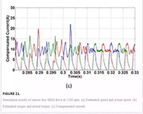
Figure 21 illustrates the simulation results for 1500 RMP. In Figure 21, estimated speed and actual speed, estimated torque and actual torque, and compensated current are exhibited.

Conclusion
This study has introduced a new phase current waveform by the 6/4 pole SRM which analyzed and simulated by means of torque ripple and acoustic noise reduction in the SRM drives. The control scheme is performed on the current profile while torque is lower than rated torque and then radial force is maximized. When both torque ripple and radial force are maximized, highest acoustic noise level can be obtained. Nonlinear relations between torque ripple and radial force on the current show that main factor in the torque ripple minimization and acoustic noise reduction is current profile. In this chapter, torque ripple and radial force have been optimized by deformation of the phase current profile by using FLC. Also, a hybrid observer scheme is described. It uses only phase currents and voltages that can be easily measured by motor terminals to estimate rotor position, speed, without extra hardware, which makes it economized. Also, online updates of gains and automatic observer selection are very effective on the speed estimation errors and position estimation errors at steady state. Moreover, current profile improvement for torque modification is used in indirect speed estimation. Simulation results have demonstrated that the motor vibrations could be reduced by the proposed method, and current waveform optimization in the SRM drive effectively decreases acoustic noise magnitude. It can be obviously seen that the method has good performance in wide range. In addition, this method effectively decreases estimation errors and torque ripple in wide speed range.