Tachometer Systems
The tachometer indicator is an instrument that shows the speed of a gas turbine engine (jet) main rotor assembly. Figure shows tachometer indicators for various types of engines. The dials of tachometer indicators used with jet engines are shown in percentage of Revolutions per Minute (RPM), based on takeoff RPM.
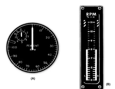
Tachometer indicators: (A) jet engine (radial); (B) jet engine (vertical scale).
Several types and sizes of generators and indicators are used in the tachometer systems of naval aircraft. As a rule, they all operate on the same basic principle. This section introduces you to information on tachometer systems. A typical generator and a typical indicator are described because it is not practical to describe all the generators and indicators. For detailed information on a particular system, you should refer to the manufacturer’s manuals.
Essentially, the tachometer system consists of an ac generator coupled to the aircraft engine and an indicator consisting of a magnetic-drag element on the instrument panel. The generator transmits electric power to a synchronous motor, a part of the indicator. The frequency of this power is proportional to the engine speed. An accurate indication of engine speed is obtained by applying the magnetic-drag principle to the indicating element. The problem of changes in generator output voltage is cut out by the generator and synchronous-motor combination. These units make a frequency-sensitive system for sending an indication of engine speed to the indicator with absolute accuracy.
For many installations, it is desirable to send a single engine-speed indication to two different stations in the aircraft. The frequency-sensitive system is ideal for this application because there is no change in indication when a second indicator connects in parallel with the first. Synchronous motor operation in each indicator depends only on the availability of enough power in the generator to operate both indicator motors.
Tachometer Generator
Tachometer generator units are small and compact (about 4 inches by 6 inches). The generator is constructed with an end shield designed so the generator can attach to a flat plate on the engine frame or reduction gearbox, with four bolts.
Figure shows a cutaway view of a tachometer generator. You should refer to it while you read this section. The generator consists essentially of a permanent magnet rotor (callout 1) and a stator (callout 8) that develop three-phase power as the rotor turns.
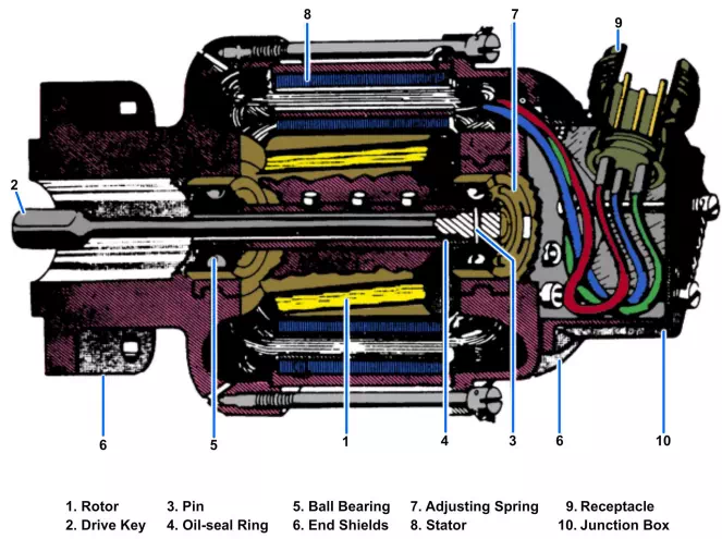
The armature of the generator consists of a magnetized rotor. The rotor is cast directly onto the generator shaft. The generator may be of either two- or four-pole construction. The two- and four-pole rotors are identical in appearance and construction. They differ in that the two-pole rotor is magnetized north and south diametrically across the rotor, while the four-pole rotor is magnetized alternately north and south at each of the four pole faces.
The key (callout 2) that drives the rotor is a long, slender shaft. It has enough flexibility to prevent failure under the torsional oscillations originating in the aircraft drive shaft. It will also accommodate small misalignments between the generator and its mounting surfaces. This key goes into the hollow rotor shaft. A pin (callout 3) at the end opposite.
the drive shaft secures the key in place. An oil-seal ring (callout 4) is located inside the hollow shaft and over this key. This seal prevents oil from leaking into the generator through the hollow shaft. The shaft runs in two ball bearings (callout 5) set in stainless steel inserts. The inserts are cast directly into the generator end shields (callout 6). An adjusting spring (callout 7) at the receptacle end of the shaft maintains the proper amount of end play.
The stator consists of a steel ring with a laminated core of ferromagnetic material. A three-phase winding goes around this core and is insulated from it. The winding is adapted for two- or four-pole construction, depending on the generator in which it is used. The two end shields are made of die-cast aluminum alloy. They serve to support the generator stator and rotor by means of a receptacle (callout 9). The receptacle attaches to the junction box (callout 10) of the generator.