Angle-Of-Attack (AOA) Indicating System
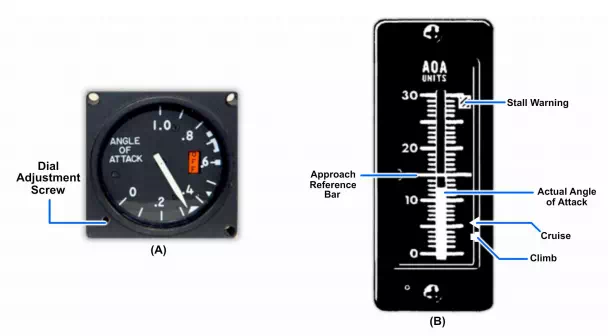
The Angle-of-Attack (AOA) indicating system detects aircraft angle of attack from a point on the side of the fuselage. It furnishes reference information for the control and actuation of other units and aircraft systems. It provides signals to operate an AOA indicator (Figure below) on the pilot’s instrument panel. This indicator displays a continuous visual indication of the local angle of attack. A typical AOA system provides electrical signals for operating the rudder pedal shaker. The shaker warns the pilot of an impending stall when the aircraft is approaching the critical stall angle of attack. Electrical switches in the AOA indicator operating at various preset angles of attack energize colored lights in the approach light system and an approach index light in the cockpit. These lights furnish the landing signal officer and the pilot with an accurate indication of approach angle of attack during landing. An angle-of-sideslip system, consisting of an airstream direction detector, and angle-of-sideslip compensator, is installed on some aircraft. The outputs from these are used for controlled rocket firing.
The AOA indicating system consists of an airstream direction detector transmitter (Figure below) and an indicator. The airstream direction detector measures local airflow direction relative to the true angle of attack. It does this by determining the angular difference between local airflow and the fuselage reference plane. The sensing element works with a servo-driven balanced bridge circuit, which converts probe positions into electrical signals.
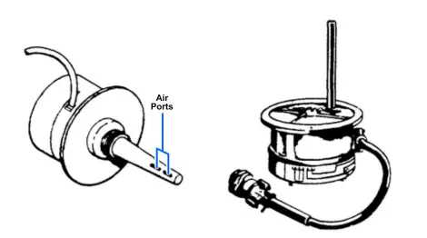
The AOA indicating system operation is based on detection of differential pressure at a point where the airstream is flowing in a direction that is not parallel to the true angle of attack of the aircraft. This differential pressure is caused by changes in airflow around the probe. The probe extends through the skin of the aircraft into the airstream.
The exposed end of the probe contains two parallel slots (ports). These slots detect the differential airflow pressure (Figure below). Air from the slots passes through two separate air passages to separate compartments in a paddle chamber. Any differential pressure, caused by misalignment of the probe to the direction of airflow, causes the paddles to rotate. The moving paddles rotate the probe, through mechanical linkage, until the pressure differential is zero. Alignment occurs when the slots are symmetrical with the airstream direction.
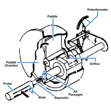
Mechanical schematic of airstream direction detector.
Two potentiometer wipers, rotating with the probe, provide signals for remote indications. Probe position, or rotation, converts into an electrical signal by the potentiometer that is the transmitter component of a self-balancing bridge circuit. When the angle of attack of the aircraft changes, the position of the transmitter potentiometer alters. The alteration causes an error voltage to exist between the transmitter potentiometer and the receiver potentiometer in the indicator.
Current flows through a sensitive polarized relay to rotate a servomotor located in the indicator. The servomotor drives a receiver potentiometer in the direction required to reduce the error voltage. This action restores the circuit to a null or electrically balanced condition. The polarity of the error voltage determines the resultant direction of rotation of the servomotor. The indicating pointer is attached to, and moves with, the receiver potentiometer wiper arm to show on the dial the relative angle of attack.
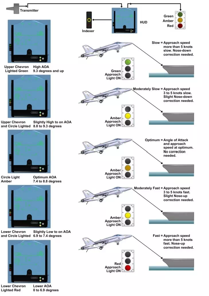
Figure shows the relationship of the AOA indexer lights indication and stall warning. The AOA indexer lights mounted on the pilot’s Heads Up Display (HUD) Combiner Assembly has two arrows and a circle illuminated by colored lamps to provide the pilot with approach information. Two Angle of Attack Transmitters (AOATs) provide angle of attack information to the flight control computers, which in turn control the AOA indexer display. The upper arrow is for high angle of attack (green). The lower arrow is for low angle of attack (red). The circle is for optimum angle of attack (amber). An arrow and a circle together show an intermediate or optimum position for landing approach.
The indexer lights function only when the landing gear is down. A flasher unit causes the indexer lights to pulsate when the arresting hook is up with the HOOK BYPASS switch in the CARRIER position.