Airspeed Indicators
Readings from an airspeed indicator are used to estimate ground speed and to determine throttle settings for the most efficient flying speed. These readings also provide a basis for calculating the best climbing and gliding angles. They warn the pilot if diving speed approaches the safety limits of the aircraft’s structure. Since airspeed increases in a dive and decreases in a climb, the indicator is an excellent check for maintaining level flight. Figure, view A, shows a cutaway view of a typical airspeed indicator.
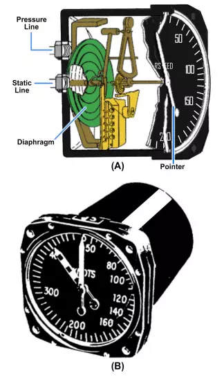
An airspeed indicator has a cylindrical, airtight case that connects to the static line from the pitot-static tube. Inside the case is a small aneroid diaphragm of phosphor bronze or beryllium copper. The diaphragm is very sensitive to changes in pressure, and it connects to the impact pressure (pitot) line. This construction allows air from the pitot tube to enter the diaphragm. The side of the diaphragm fastens to the case and is rigid. The needle or pointer connects through a series of levers and gears to the free side of the diaphragm.
The airspeed indicator is a differential pressure instrument. It measures the difference between the pressures in the impact pressure line and in the static pressure line. The two pressures are equal when the aircraft is stationary on the ground. Movement through the air causes pressure in the impact line to become greater than that in the static line. This pressure increase causes the diaphragm to expand. The expansion or contraction of the diaphragm goes through a series of levers and gears to the face of the instrument to regulate needle position. The needle shows the pressure differential in MPH or knots. All speeds and distances are in nautical miles.
Maximum Allowable Airspeed Indicator
Figure view B, shows the face of a maximum allowable airspeed indicator. The dial face measurements are in knots from 50 to 450 with an expanded scale below 200 knots. The dial has an indicating pointer and a maximum safe airspeed pointer. The maximum safe airspeed pointer moves as the maximum safe airspeed changes because of static pressure changes at different altitudes.
No matter where the pitot-static tube is located, it is impossible to keep it free from all air disturbances set up by the aircraft structure. You must make allowances for this installation error when reading the indicator. Temperature is another cause of error. Also, imperfect scaling of the indicator dial with respect to the airspeed differential pressure relationship will cause an error in reading. You can make simple adjustments to the instrument mechanism to correct the tendency to read fast or slow.
Mach Speed Indicators
In some cases, the term Mach speed is used to express aircraft speed. The Mach speed is the ratio of the speed of a moving body to the speed of sound in the surrounding medium. For example, if an aircraft is flying at a speed equal to one-half the local speed of sound, it is flying at Mach 0.5. If it moves at twice the local speed of sound, its speed is Mach 2.
Figure shows the front view of a typical airspeed and Mach speed indicator. The instrument consists of altitude and airspeed mechanisms incorporated in a single housing. This instrument gives the pilot a simplified presentation of both indicated airspeed and Mach speed. Both indications are read from the same pointer.
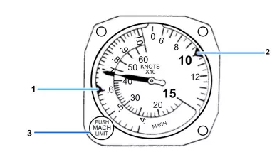
The pointer shows airspeed at low speeds, and both indicated airspeed and Mach speed at high speeds. Pitot pressure on a diaphragm moves the pointer, and an aneroid diaphragm controls the Mach speed dial. The aneroid diaphragm reacts to static pressure changes because of altitude changes. Figure is a mechanical schematic of an airspeed and Mach speed indicator.
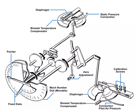
Airspeed/Mach speed indicator mechanical schematic.
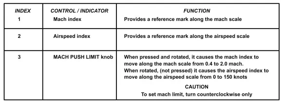
The range of the instrument is 80 to 650 knots indicated airspeed and from 0.5 to 2.0 Mach speed. Its calibrated operating limit is 50,000 feet of altitude. A stationary airspeed dial masks the upper range of the movable Mach dial at low altitudes. The stationary airspeed dial is graduated in knots. The instrument incorporates a landing speed index and a Mach speed setting index. You can adjust both indexes by a knob on the lower left-hand corner of the instrument. You can adjust the landing speed index over a range of 80 to 150 knots. The index operates with the knob in its normal position. You may adjust the Mach speed index over the entire Mach range. The index adjusts by depressing the knob and turning it.