Analysis of Perfect Frames (Graphical Method)
INTRODUCTION
In the previous chapter, we have discussed the analytical methods for determining the forces in perfect frames. We have seen that the method of joints involves a long process, whereas the method of sections is a tedious one. Moreover, there is a possibility of committing some mathematical mistake, while finding out the forces in the various members of truss. The graphical method, for determining the forces in the members of a perfect frame, is a simple and comparatively fool-proof method. The graphical solution of a frame is done in the following steps:
1. Construction of space diagram,
2. Construction of vector diagram and
3. Preparation of the table.
CONSTRUCTION OF SPACE DIAGRAM
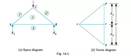
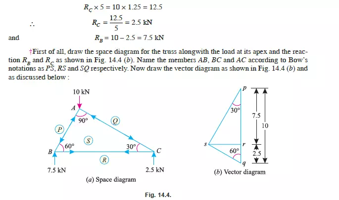
It means the construction of a diagram of the given frame to a suitable linear scale, alongwith the loads it carries. The magnitude of support reactions is also found out and shown in the space
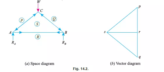
diagram. Now name the various members and forces according to Bow’s notations as shown in Fig. 14.1 (a). In the space diagram of the truss ABC shown in Fig. 14.1 (a), the members AB, BC and CA are represented by SR (or RS), SQ (or QS) and PS (or SP) respectively. Similarly, load at C and reactions at A and B are represented by PQ, RP and QR respectively.
Note: The reactions are generally found out by analytical method as discussed in the last chapter.
CONSTRUCTION OF VECTOR DIAGRAM
After drawing the space diagram and naming the various members of the frame according to Bow’s notations, as discussed in the last article, the next step is the construction of vector diagram. It is done in the following steps :
1. Select a suitable point p and draw pq parallel to PQ (i.e., vertically downwards) and equal to the load W at C to some suitable scale.
2. Now cut off qr parallel to QR (i.e., vertically upwards) equal to the reaction RB to the scale.
3. Similarly, cut off rp parallel to RP (i.e., vertically upwards) equal to the reaction RA to the scale. Thus we see that in the space diagram, we started from P and returned to P after
going for P-Q-R-P (i.e., considering the loads and reactions only).
4. Now through p draw a line ps parallel to PS and throgh r draw rs parallel to RS, meeting the first line at s as shown in Fig. 14.1 (b). Thus psrp is the vector diagram for the joint (A).
5. Similarly, draw the vector diagram qrsq for the joint (B) and pqsp is the vector diagram for the joint (C) as shown in Fig. 14.1 (b).
Notes: 1. While drawing the vector diagram, for a joint, care should be taken that the joint under consideration does not contain more than two members whose forces are unknown. if the joint, under consideration contains more than two such members whose forces are unknown, then some other joint which does not contain more than two unknown force members, should be considered for drawing the vector diagram.
2. If at any stage (which normally does not arise in a perfect frame) the work of drawing the vector diagram is held up at some joint, it will be then necessary to determine the force at such a
joint by some other method i.e., method of sections or method of joints.
FORCE TABLE
After drawing the vector diagram, the next step is to measure the various sides of the vector diagram and tabulate the forces in the members of the frame. For the preparation of the table, we
require :
1. Magnitude of forces, and
2. Nature of forces.
MAGNITUDE OF FORCE
Measure all the sides of the vector diagram, whose lengths will give the forces in the corresponding members of the frame to the scale e.g., the length ps of the vector diagram will give the
force in the member PS of the frame to the scale. Similarly, the length sr will give the force in the member SR to the scale and so on as shown in Fig. 14.2. (b). If any two points in the vector diagram coincide in the each other, then force in the member represented by the two letters will be zero.
NATURE OF FORCE
The nature of forces in the various members of a frame is determined by the following steps:
1. In the space diagram, go round a joint in a clockwise direction and note the order of the two letters by which the members are named e.g., in Fig. 14.2 (a) the members at joint (A)
are RP, PS and SR. Similarly, the members at joint (B) are QR, RS and SQ. And the members at joint (C) are PQ, QS and SP.
2. Now consider a joint of the space diagram and note the order of the letters of all the members (as stated above). Move on the vector diagram in the order of the letters noted on the space diagram.
3. Make the arrows on the members of the space diagram, near the joint, under consideration, which should show the direction of movement on the vector diagram. Put another arrow in the opposite direction on the other end of the member, so as to indicate the equilibrium of the method under the action of the internal stress.
4. Similarly, go round all the joints and put arrows.
5. Since these arrows indicates the direction of the internal forces only, thus the direction of the actual force in the member will be in opposite direction of the arrows, e.g., a member
with arrows pointing outwards i.e., towards the joints [as member PS and SQ of Fig. 14.2 (a)] will be in compression; whereas a member with arrow pointing inwards i.e., away from
the joints [as member SR in Fig. 14.2 (b)] will be in tension.
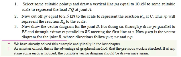
Example 14.1. The truss ABC shown in Fig. 14.3 has a span of 5 metres. It is carrying a load of 10 kN at its apex.
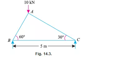
Find the forces in the members AB, AC and BC
Solution*. From the geometry of the truss, we find that the load of 10 kN is acting at a distance of 1.25 m from the left hand support i.e., B and 3.75 m from C. Taking moments about B and
equating the same,