Analysis of Perfect Frames
INTRODUCTION
A frame may be defined as a structure, made up of several bars, riveted or welded together. These are made up of angle irons or channel sections, and are called members of the frame or framed structure. though these members are welded or riveted together, at their joints, yet for calculation purposes, the joints are assumed to be hinged or pin-jointed. The determination of force in a frame is an important problem in engineering- science, which can be solved by the application of the principles of either statics or graphics. in this chapter, we shall be using the
principles of statics for determining the forces in frames.
TYPES OF FRAMES
Though there are many types of frames, yet from the analysis point of view, the frames may be
classified into the following two groups:
1. Perfect frame.
2. Imperfect frame.
PERFECT FRAME
A perfect frame is that, which is made up of members just sufficient to keep it in equilibrium, when loaded, without any change in its shape.
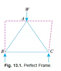
The simplest perfect frame is a triangle, which contains three members and three joints as shown in Fig. 13.1. It will be intersting to know that if such a structure is loaded, its shape will not be distorted. Thus, for three jointed frame, there should be three members to prevent any distortion. It will be further noticed that if we want to increase a joint, to a triangular frame, we require two members as shown by dotted lines in Fig. 13.1. Thus we see that for every additional joint, to a triangular frame, two members are required. The no. of members, in a perfect frame, may also be expressed by the relation :
n = (2j – 3)
n = No. of members, and
j = No. of joints.
IMPERFECT FRAME
An imperfect frame is that which does not satisfy the equation :
n = (2j – 3)
Or in other words, it is a frame in which the no. of members are more or less than (2j – 3). The imperfect frames may be further classified into the following two types :
1. Deficient frame.
2. Redundant frame.
DEFICIENT FRAME
A deficient frame is an imperfect frame, in which the no. of members are less than (2j – 3).
REDUNDANT FRAME
A redundant frame is an imperfect frame, in which the no. of members are more than (2j – 3).
In this chapter, we shall discuss only perfect frames.
STRESS
When a body is acted upon by a force, the internal force which is transmitted through the body is known as stress. Following two types of stress are important from the subject point of view :
1. Tensile stress.
2. Compressive stress.
TENSILE STRESS
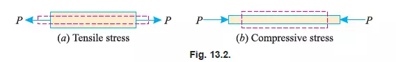
Sometimes, a body is pulled outwards by two equal and opposite forces and the body tends to extend, as shown in Fig 13.2. (a). The stress induced is called tensile stress and corresponding force is called tensile force.
COMPRESSIVE STRESS
Sometimes, a body is pushed inwards by two equal and opposite forces and the body tends to shorten its length as shown in Fig. 13.2 (b). The stress induced is called compressive stress and the corresponding force is called compressive force.
ASSUMPTIONS FOR FORCES IN THE MEMBERS OF A PERFECT FRAME
Following assumptions are made, while finding out the forces in the members of a perfect frame:
1. All the members are pin-jointed.
2. The frame is loaded only at the joints.
3. The frame is a perfect one.
4. The weight of the members, unless stated otherwise, is regarded as negligible in comparison with the other external forces or loads acting on the truss.
The forces in the members of a perfect frame may be found out either by analytical method or graphical method. But in this chapter, we shall discuss the analytical method only.
ANALYTICAL METHODS FOR THE FORCES
The following two analytical methods for finding out the forces, in the members of a perfect frame, are important from the subject point of view :
1. Method of joints.
2. Method of sections.
METHOD OF JOINTS
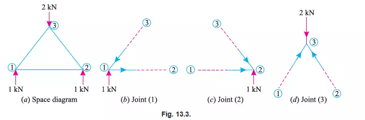
In this method, each and every joint is treated as a free body in equilibrium as shown in Fig. 13.3 (a), (b), (c) and (d). The unknown forces are then determined by equilibrium equations viz.,
Ó V = 0 and Ó H = 0. i.e., Sum of all the vertical forces and horizontal forces is equated to zero
Notes: 1. The members of the frame may be named either by Bow’s methods or by the joints at their ends.
2. While selecting the joint, for calculation work, care should be taken that at any instant, the joint should not contain more than two members, in which the forces are unknown.
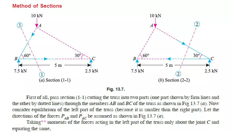
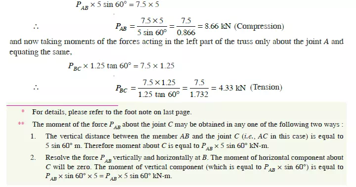
METHOD OF SECTIONS (OR METHOD OF MOMENTS)
This method is particularly convenient, when the forces in a few members of a frame are required to be found out. In this method, a section line is passed through the member or members, in
which the forces are required to be found out as shown in Fig. 13.4 (a). A part of the structure, on any one side of the section line, is then treated as a free body in equilibrium under the action of external forces as shown in Fig. 13.4 (b) and (c).
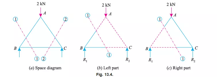
The unknown forces are then found out by the application of equilibrium or the principles of statics i.e., Ó Ì = 0.
Notes:1. To start with, we have shown section line 1-1 cutting the members AB and BC. Now in order to find out the forces in the member AC, section line 2-2 may be drawn.
2. While drawing a section line, care should always be taken not to cut more than three members, in which the forces are unknown.
FORCE TABLE
Finally, the results are tabulated showing the members, magnitudes of forces and their
nature. Sometimes, tensile force is represented with a + ve sign and compressive force with a
– ve sign.
Note: The force table is generally prepared, when force in all the members of a truss are
required to be found out.
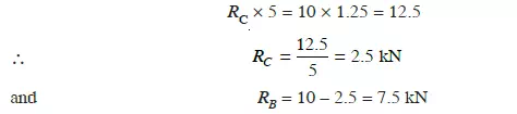
Example 13.1. The truss ABC shown in Fig. 13.5 has a span of 5 metres. It is carrying a
load of 10 kN at its apex.
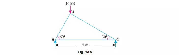
Find the forces in the members AB, AC and BC.
Solution. From the geometry of the truss, we find that the load of 10 kN is acting at a
distance 1.25 m from the left hand support i.e., B and 3.75 m from C. Taking moments about B and
equating the same,
Methods of Joints
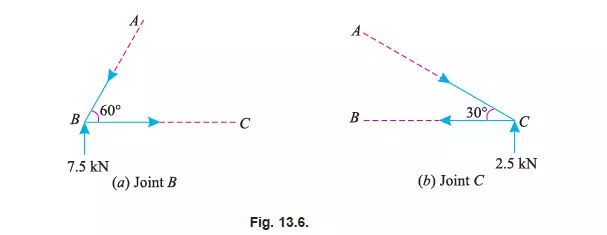
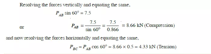
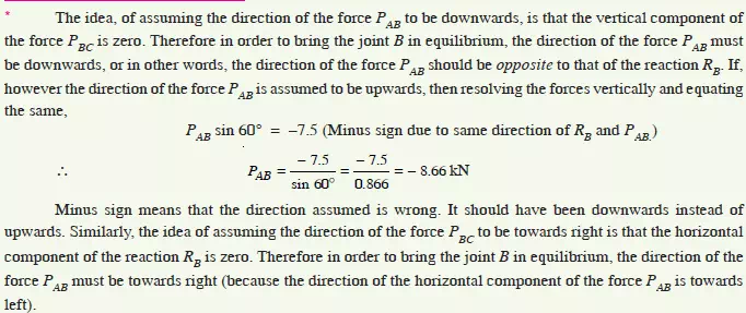
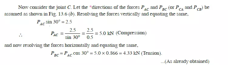
First of all consider joint B. Let the *directions of the forces PAB and PBC (or PBA and PCB) be
assumed as shown in Fig 13.6 (a).