Simple Lifting Machines
INTRODUCTION
In the last chapter, we have discussed the principles of lifting machines. Now in this chapter, we shall discuss the applications of these principles on a few lifting machines.
TYPES OF LIFTING MACHINES
These days, there are many types of lifting machines which are available in the market. But the basic principle, on which all these machines are based, is the same. It will be interesting to know that engineers who have designed (or invented) these machines have tried to increase the velocity ratio of their respective lifting machines. A little consideration will show, that if the efficiency of a machine remains almost the same, then increase in the velocity ratio must increase its mechanical advantage. The increased mechanical advantage, of a machine, means the application of a smaller force to lift the same load; or to lift a heavier load with the application of the same force. The following lifting machines, which are important from the subject point of view, will be
discussed in the following pages:
1. Simple wheel and axle.
2. Differential wheel and axle.
3. Weston’s differential pulley block.
4. Geared pulley block.
5. Worm and worm wheel.
6. Worm geared pulley block.
7. Single purchase crab winch.
8. Double purchase crab winch.
9. Pulleys:
(a) First system of pulleys.
(b) Second system of pulleys.
(c) Third system of pulleys.
10. Simple screw jack.
11. Differential screw jack.
12. Worm geared screw jack.
SIMPLE WHEEL AND AXLE
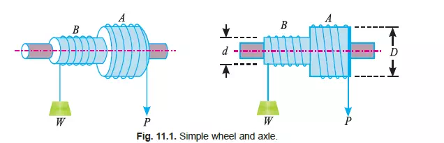
In Fig. 11.1 is shown a simple wheel and axle, in which the wheel A and axle B are keyed to the same shaft. The shaft is mounted on ball bearings, order to reduce the frictional resistance to a
minimum. A string is wound round the axle B, which carries the load to be lifted. A second string is wound round the wheel A in the opposite direction to that of the string on B.
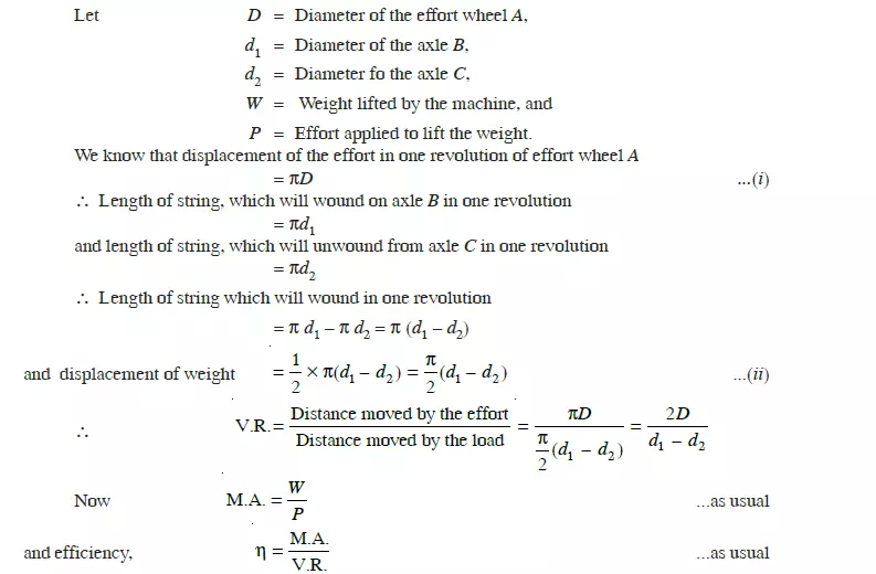
Let D = Diameter of effort wheel,
d = Diameter of the load axle,
W = Load lifted, and
P = Effort applied to lift the load.
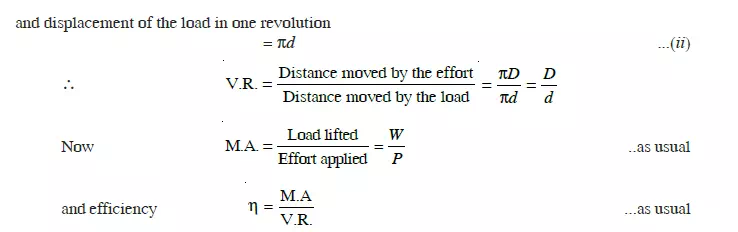
One end of the string is fixed to the wheel, while the other is free and the effort is applied to this end. Since the two strings are wound in opposite directions, therefore a downward motion of the effort (P) will raise the load (W). Since the wheel as well as the axle are keyed to the same shaft, therefore when the wheel rotates through one revolution, the axle will also rotate through one revolution. We know that displacement of the effort in one revolution of effort wheel A, = ðD ...(i)
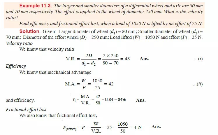
DIFFERENTIAL WHEEL AND AXLE
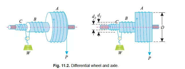
It is an improved form of simple wheel and axle, in which the velocity ratio is intensified with the help of load axle. In fig. 11.2 is shown a differential wheel and axle. In this case, the load axle BC is made up of two parts of different diameters. Like simple wheel and axle, the wheel A, and the axles B and C are keyed to the same shaft, which is mounted on ball bearings in order to reduce the frictional resistance to a minimum. The effort string is wound round the wheel A. Another string wound round the axle B, which after passing round the pulley (to which the weigt W is attached) is wound round the axle C in opposite direction to that of the axle B; care being taken to wind the string on the wheel A and axle C in the same direction. As a result of this, when the string unwinds from the wheel A, the other string also unwinds from the axle C. But it winds on the axle B as shown in Fig. 11.2.