Seepage through soils
Introduction
'Seepage' is defined as the flow of a fluid, usually water, through a soil under a hydraulic gradient. A hydraulic gradient is supposed to exist between two points if there exists a difference in the 'hydraulic head ' at the two points. By hydraulic head is meant the sum of the position or datum head and pressure head of water. The discussion on flow nets and seepage relates to the practicql aspect of controlling groundwater during and after construction of foundations below the groundwater table, earth dam and weirs on permeable foundations.
The interaction between soils and percolating water has an important influence on:
1. 1 . The design of foundations and earth slopes,
2. The quantity of water that will be lost by percolation through a dam or its subsoil.
Foundation failures due to 'piping' are quite common. Piping is a phenomenon by which the soil on the downstream sides of some hydraulic structures get lifted up due to excess pressure of water. The pressure that is exerted on the soil due to the seepage of water is called the seepage force or pressure. In the stability of slopes, the seepage force is a very important factor. Shear strengths of soils are reduced due to the development of neutral stress or pore pressures. A detailed understanding of the hydraulic conditions is therefore essential for a satisfactory design of structures.
Two dimensional flow- Laplace equation
In many instances, the flow of water through soil is not in one direction only, nor is it uniform over the entire area perpendicular to the flow. In such cases, the groundwater flow is generally calculated by the use of graphs referred to as flow nets. The concept of the flow net is based on Laplace's equation of continuity, which governs the steady flow condition for a given point in the soil mass.
Laplace's Equation of Continuity
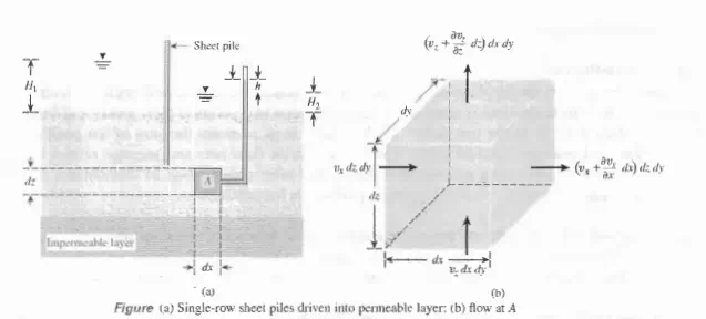
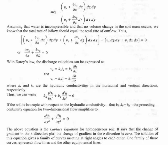
To derive the Laplace differential equation of continuity, let us consider a single row of sheet piles that have been driven into a permeable soil layer, as shown in Figure a. The row of sheet piles is assumed to be impervious. The steady state flow of water from the upstream to the downstream side through the permeable layer is a two-dimensional flow. For flow at a point A, we consider an elemental soil block. The block has dimensions dx, dy, and dz (length dy is perpendicular to the plane of the paper); it is shown in an enlarged scale in Figure b. Let Vx and v2 be the components of the discharge velocity in the horizontal and vertical directions, respectively. The rate of flow of water into the elemental block in the horizontal direction is equal to Vx dz dy, and in the vertical direction it is v2 dx dy. The rates of outflow from the block in the horizontal and ve1iical directions are, respectively,