On Farm Structures for Water Conveyance
It is necessary that the flow of irrigation water in the water conveyance system is always under control. Water control structures are therefore required for water conveyance system to control the flow of water and dispose at safer velocity. The different types of flow control structures used to regulate water flow are presented in this lesson
Drop Structures
Drop structure is used for conveying water in the channel from higher elevation to lower elevation while controlling the energy and velocity of the water as it passes over. These structures are needed in canals and ditches to convey water down steep slopes at non-erosive velocities. Drop structure is constructed at end of each reach to lower water head abruptly in to the next reach by subdividing the slope in to several reaches with relatively flat slopes. Water is conveyed down the slope in the stepwise manner. The components of drop structure include an inlet section, a vertical or inclined drop, a stilling pool or other means of dissipating energy, and an outlet section for discharging water into the next reach. Kruse et al., (1980) recommend that drop heights in conveyance canals and ditches be limited to maximum of 0.6 m to 1 m and that drop height in distribution laterals be less than 15 to 30 cm. Fig. 13.1 shows series of drop structures on a steep sloping land.
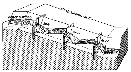
Fig. 13.1. A view of Drop structures in a canal on steep sloping land.
Chute Spillways
These are used to convey water from steep slopes. Chutes are lined, high-velocity open channels (Fig. 13.2 and 13.3). Chute structures are constructed with concrete, bricks or cement. They have an inlet, a steep-sloped section of lined canal where the elevation change occurs, a stilling pool or other energy dissipation device, and an outlet section. Chutes may be made to control flow for elevation changes up to 6m. A straight apron is used for small structure used in small irrigation channel.
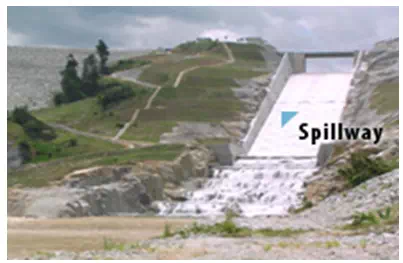
Fig. 13.2. Chute spillway.
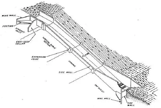
Fig. 13.3. Section of Chute spillway.
Pipe Drop Spillways
Pipe drop structure (Fig. 13.4) is used where a channel has to cross an embankment. In such cases water can be safely discharged from a higher to a lower one by providing a pipe drop. This type of structure allows the discharge of water through a pipeline, without disturbing the existing bunds or embankment. The components of structures are gated pipe, stilling basin with end sill. Stilling basin is provided for dissipation of energy of water flow. A stilling basin is made up of brick or stone masonry, or concrete. A masonry or concrete apron is provided at the inlet end of the pipe to prevent seepage around it. The discharge capacity of the pipe drop structure may be determined by the relationship
Q = A V
in which,
Q = discharge (m3s-1)
A= area of cross-section of the pipe (m2)
V = velocity of flow (m/sec)
In designing the pipe size, head loss due to friction in the pipe line, entrance losses and loss at the bends are considered.
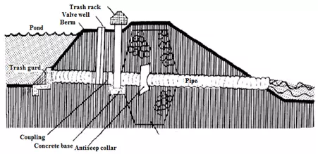
Fig. 13.4. A drop-inlet pipe spillway with drain pipe.
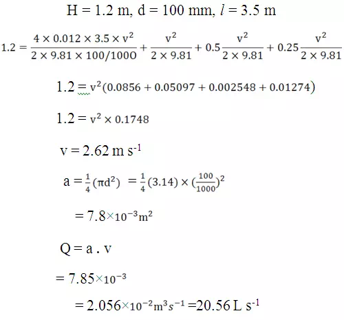
Example1:
Determine the capacity of 3.5 m long (l) pipe of pipe drop spillway to be used for effective drop in head (H) as 1.2 m. The diameter of pipe (d) is 100 mm and friction coefficient (f) is 0.012.
Solution:
The applicable formula for the total head in pipe drop spillway is
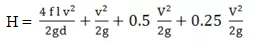
where
v = velocity of flow and g = acceleration due to gravity
Substituting the values is above equation