Electrical Power for Agricultural Machines
Electric motors are devices that convert electric power into mechanical power. They are often chosen over engines for applications in which an electrical power supply is available. Compared to engines, electric motors are quieter, more readily adaptable to automatic or remote control, and do not produce exhaust emissions. Unlike engines, which will stall and stop consuming fuel when overloaded, an electric motor will continue to absorb electricity when overloaded. To prevent self-destruction, therefore, means must be provided to prevent an electric motor from overheating and breaking down the insulation on the windings. Typically, a thermal protector is provided to disconnect the electrical power when the windings reach a limiting temperature.
Motor Components
A wide variety of electric motors are in commercial use, but all motors have certain features in common. A frame holds all parts in their proper orientation. Bearings (sleeve, roller, or ball) hold the rotating shaft in the frame. The stator includes electrical windings on a laminated magnetic core. The windings are arranged to provide at least two electrical poles, that is, a north and a south pole. Electric current flowing through the windings produces a magnetic field across a rotor, which rotates with the motor shaft. A fan within motors helps to provide cooling. The housings of some electric motors have external fins to aid in cooling. A terminal housing with a removable cover is attached to motors to allow access to the certain wires within the motor. On most motors, a means of terminating an equipment grounding wire is provided in the terminal housing. Finally, information relating to the internal wiring and the motor application is given on a nameplate attached to the motor.
Motor Classifications
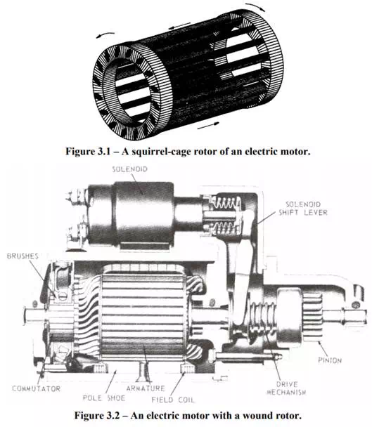
There are four classification systems that help to describe the differences between motors. First, motors can be classified as to the type of electrical power required, that is, alternating current (AC) or direct current (DC). Secondly, the electrical power can be single-phase (1-φ) or three-phase (3-φ). The rotor can be designed as a squirrelcage or a wound rotor. The squirrel-cage design is less expensive because it has no windings; rather, induced currents flow in the bars and end plates (Figure 3.1). A wound rotor has many loops of wire wrapped on the rotor; the wound rotor in Figure 3.2 is for a DC motor used as an electric starter, but AC motors with wound rotors are also available. The loops terminate at commutator segments on which stationary brushes can ride to make electrical contract with the loop connected to a particular set of commutators. Rotors containing such windings and commutators are called armatures. Finally, motors can be classified as induction or synchronous motors. Synchronous motors turn at a speed that is governed by the frequency of the electrical voltage and the number of poles but is independent of motor load. Conversely, loading of induction motors causes slippage, which in turn causes the rotor to turn slower than the synchronous speed. Most of the rest of this chapter is concerned with AC, induction-type motors with a squirrel-cage rotor, since these motors are in the most widespread use. Smaller motors of this design run on single-phase power, while threephase power is used for larger motors. DC motors will also be discussed. Other types of electrical motors will be described only briefly.