Underwater Optical Wireless Communication Systems: A Concise Review
Abstract
Underwater optical wireless communications (UOWC) have gained a considerable interest during the last years as an alternative means for broadband inexpensive submarine communications. UOWC present numerous similarities compared to free space optical (FSO) communications or laser satellite links mainly due to the fact that they employ optical wavelengths to transfer secure information between dedicated point‐to‐point links. By using suitable wavelengths, high data rates can be attained. Some recent works showed that broadband links can be achieved over moderate ranges. Transmissions of several Mbps have been realized in laboratory experiments by employing a simulated aquatic medium with scattering characteristics similar to oceanic waters. It was also demonstrated that UOWC networks are feasible to operate at high data rates for medium distances up to a hundred meters. However, it is not currently available as an industrial product and mainly test‐bed measurements in water test tanks have been reported so far. Therefore, extensive research is expected in the near future, which is necessary in order to further reveal the “hidden” abilities of optical spectrum to transfer broadband signals at higher distances. The present work summarizes the recent advances in channel modeling and system analysis and design in the area of UOWC.
Introduction
The present work summarizes the recent advances in channel modeling and system analysis and design in the area of underwater optical wireless communications (UOWC). UOWC have gained a considerable interest during the last years as an alternative means for broadband inexpensive submarine communications.
The technology that is mostly used nowadays among divers, ships, etc. is mainly based on acoustic wave transmission. However, it is restricted to several hundreds of kbps at ranges of a few kilometers, supports slow data rates, and distresses marine mammals such as dolphins and whales. On the other hand, traditional electromagnetic (EM) waves are highly attenuated in water due to both absorption and scattering. Therefore, they can be used only for relatively short‐range real‐time applications in the order of a few centimeters to a few meters.
EM waves in the visible spectrum, for example, optical signals between 400 and 700 nm, propagate faster in water than acoustic ones. However, the optical transmitters and receivers must be located at a short distance, since turbulence and multiscattering effects significantly deteriorate the performance. Chromatic dispersion also causes temporal broadening of the optical pulses. In contrast to the above impairments, seawater shows a decreased absorption in the blue/green region of the visible spectrum. Hence, using suitable wavelengths, high data rates can be attained. Moreover, some recent works showed that broadband links can be achieved over moderate ranges. Transmissions of several Mbps have been realized in laboratory experiments by employing a simulated aquatic medium with scattering characteristics similar to oceanic waters. It was also demonstrated that UOWC networks are feasible to operate at high data rates for medium distances up to a hundred meters.
UOWC present numerous similarities compared to free space optical (FSO) communications or laser satellite links mainly due to the fact that they employ optical wavelengths to transfer secure information between dedicated point‐to‐point links. It constitutes an alternate and effective transmission technique for underwater communications, instead of the traditional acoustic one. However, it is not currently available as an industrial product and mainly test‐bed measurements in water test tanks have been reported so far. Therefore, extensive research is expected in the near future which is necessary in order to further reveal the “hidden” abilities of optical spectrum to transfer broadband signals at higher distances.
In the current chapter, we outline the main characteristics of UOWC channel models based on theoretical and experimental results, the phenomena limiting their performance, and the key research trials reported so far for this novel branch of optical wireless systems. A brief review of acoustic and EM communication techniques is also presented, which helps the readers better understand the different ways UOWC operates.
Wave transmission in the aquatic medium
ACOUSTIC WAVES
Until today, underwater transmission is attained by employing acoustic waves. This technology supports, relatively, low data rates for medium distances and does not ensure the link security. Furthermore, the information signal delay is quite increased. It is a legacy technology, and even it works at long distances, it can only establish low speed transmissions. Therefore, it is inappropriate for broadband transmission driven by the current and ongoing communication demands.
Although sound travels decently through air, it travels much better through water. The speed of sound in clear air is 340 m/s, which is almost four times smaller than the speed of sound in water, which is 1500 m/s. However, it is much smaller than the speed of light and EM waves.
The speed at which sound travels through water is highly dependent on the temperature, pressure, and salinity of the water. While the sound waves travel through water, the energy is absorbed by the aquatic medium and can be transformed to other forms, such as heat. Roughly speaking, the main impairments of underwater acoustic transmission are presented in the sequel.
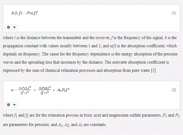
Path Loss: The attenuation or path loss in an underwater channel is frequency dependent and expressed as
Multipath: The multipath propagation is a common problem for underwater acoustic links and causes the acoustic signals to reach the receiver following different multiple paths. In general, reflected waves from the bottom, from the surface, or from other objects are received from the transmitter. Moreover, sound speed variations with depth create wave refraction. As a result, the receiver detects more than one pulses with a different amplitude phase and instant of arrival. An efficient expression for the channel impulse response is the following

The transmission range, the depth, the geometry of the channel, the frequency, and the sound speed profile are the main factors that create multipath effects. As a result, horizontal channels (according to the direction of the wave with respect of the ocean bottom) exhibit longer multipath spreads, whereas vertical channels have little time dispersion. Multipath propagation can severely deteriorate the acoustic signal as it generates intersymbol interference (ISI).
Noise: Noise is created by machines which are in use or by shipping activities usually in high traffic areas. Another kind of noise is ambient noise, which is mostly related to hydrodynamics caused by the movement of water from one place to another like currents or tides. Weather effects on the sea like winds, rains, storms, atmospheric turbulence, thermal noise, seismic, and biological phenomena can also induce noise. The primary sources of noise in shallow waters seem to be created by ships and snapping shrimps.
Doppler spread: Doppler frequency spread is caused by the relative motion between the transmitter and the receiver. ISI is also related to Doppler spread mostly in high data rate transmissions where adjacent symbols interfere at the receiver. The Doppler effect can be estimated by the ratio a = Ur/c where Ur is the relative velocity between the transmitter and the receiver, and c is the signal propagation speed. The Doppler factor is about a = 10−4 due to the relatively low frequency of the acoustic signals inside water (1500 m/s).
Even at short ranges, the acoustic channel is limited to low data rates under Mbps. For medium ranges (1–10 km), the data rate drops to approximately 10 kbps, and eventually at very long ranges (>100 km), the data rate is less than 1 kbps. Therefore, the acoustic wave transmission cannot satisfy the needs of new demanding technologies because of the inability to achieve high data rate communications in real‐time operation.
EM WAVES
EM waves in the RF band can be used in order to achieve faster wireless transmission. They are also unaffected by temperature and depth. Attenuation is the main effect of water in all EM waves, due to both absorption and scattering. EM wave behavior in freshwater and seawater is quite different and that is due to the fact that sea water is a high‐loss medium. Propagation velocity and the absorptive loss of EM waves can be described as functions of carrier frequency.
EM waves inside water are highly frequency dependent and proportional to the square root of frequency. This is the main reason for using low frequencies VLF and ELF. VLF band consists of radio waves between 3 and 30 kHz, can achieve data rates of 300 bit/s, and is able to penetrate seawater at a depth of 20 m. ELF band (3–300 Hz) can penetrate seawater at depths of hundreds of meters, something quite useful for communications between submarines.
To sum up, the main limitations of EM waves are the big antenna size needed in freshwater and the high attenuation for seawater. Available commercial products for underwater in RF band can achieve bit rates of 100 bps for a range of several decades of meters. 1–10 Mbps within 1 m range has been reported, as well.
OPTICAL WAVES
Optical wireless communications are a relatively new technology providing many serious advantages, such as the very high rates of data transmission, secure links, very small and light size of the transceiver components, including apertures, low installation and operational cost, and no need of licensing fees and tariffs, since the optical band is not included in the telecommunications regulations. Optical wireless uses modulated optical beams in order to establish short, medium or long communications. Unfortunately, because the propagation medium is the free space, the performance and the reliability of these systems depend mainly on the weather conditions between the receiver and the transmitter.
EM waves in the visible spectrum (400–700 nm) present an alternative way to provide broadband communications in the water. They propagate faster in water (300,000,000 m/s) than the acoustic ones (∼340 m/s in air–∼1500 m/s in water), which is about 200,000 times faster than sound travels through water. That is the main reason why they have gained a considerable interest during the last years to serve as a broadband (10–100 Mbps), safe (non‐interceptable), and reliable complement to legacy acoustic underwater communications systems.
In general, optical signals are highly absorbed in water, and this is one of the main disadvantages; the other one is the optical scattering by all the particles existing inside the sea. However, seawater shows a decreased absorption in the blue/green region of the visible spectrum. Thus, using suitable wavelengths, for instance in the blue/green region, high speed connections can be attained according to the type of water (400–500 nm for clear to 300–700 nm for turbid water conditions). Minimum attenuation is centered near 0.460 μm in clear waters and shifts to higher values for dirty waters approaching 0.540 μm for coastal waters.
Roughly speaking, the power received P(z), given initial power P0, propagating through a medium of thickness z is estimated by the Beer’s Law as follows
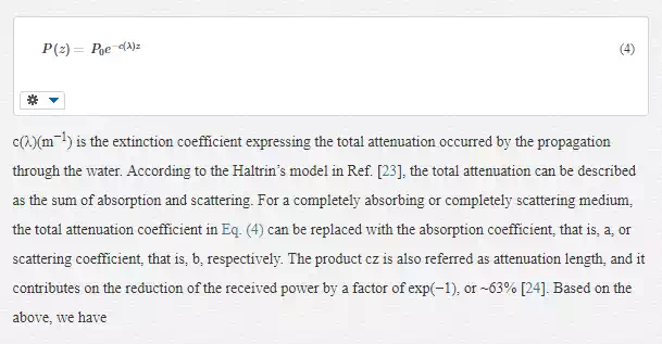

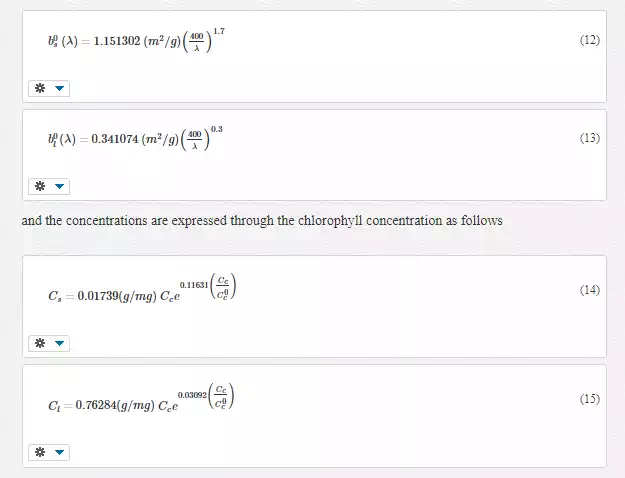
where a(λ) is the absorption coefficient, b(λ) is the scattering coefficient, and λ is the wavelength.
Beer’s Law provides a limited applicability as it describes only the attenuation due to absorption and single scattering events. In reality, however, many cases of multiple scattering may occur. Also it presumes that the source and receiver are in exact alignment with each other, and it can be applied only in Line‐of‐Sight (LOS) communication scenarios. Moreover, Beer’s Law ignores temporal dispersion.
More accurate expressions have to take the link geometry into account. For instance, assuming that the transmitter and receiver are positioned in a LOS configuration, the received power can be estimated by
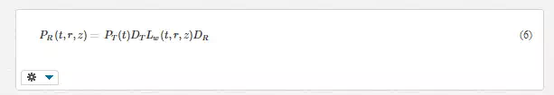
where PR(t, r, z) is the received power dependent on time t, lateral displacement from the beam axis r, and range z, PT (t) represents the transmitted power, DT is the aperture and divergence of the optical source, and DR is the photoreceiver aperture and field of view. The channel loss term, LW (t, r, z), characterizes the spatial and temporal characteristics of light propagation in seawater.
UOWC propagation phenomena
AQUATIC MEDIUM CHARACTERISTICS
The aquatic medium contains almost 80 different elements, dissolved or suspended in pure water, with different concentrations. Some of them are listed below
· Various dissolved salts such as NaCl, MgCl2, etc, which absorb light at specific wavelengths and induce scattering effects.
· Detrital and mineral components, for example, sand, metal oxides, which contribute to both absorption and scattering.
· Colored dissolved organic matters such as fulvic and humic acids which affect absorption, mainly in blue and ultraviolet wavelengths.
· Organic matters such as viruses, bacteria, and organic detritus which add backscattering, especially in the blue spectral range.
· Phytoplankton with chlorophyll‐A which strongly absorbs in the blue‐red region and scatters green light.
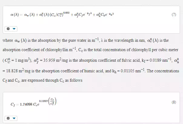
Since chlorophyll absorbs the blue and red wavelengths and the particles strongly contribute to the scattering coefficient, we can use its concentration C (in mg/m3) as the free parameter to calculate the absorption and scattering coefficients.
The exact type of water plays a significant role in the estimation of the amount of chlorophyll concentration and consequently the amount of absorption and scattering for a specific geographic location. A classification system for the clarity of water types based on their spectral optical attenuation depth zk=1kd/zk=1kd was proposed by Jerlov in 1968. This classification was made in the upper portions of the ocean, and it was based on spectral irradiance transmittance measurements. The four major water types that are usually referred in the literature are the following
· Pure deep ocean waters cobalt blue where the absorption is high and the scattering coefficient is low.
· Clear sea waters with higher scattering due to many dissolved particles.
· Near coasts ocean waters with absorption and scattering due to planktonic matters, detritus, and mineral components.
· Harbor murky waters, which are quite constraining for optical propagation due to dissolved and in‐suspension matters.
ABSORPTION
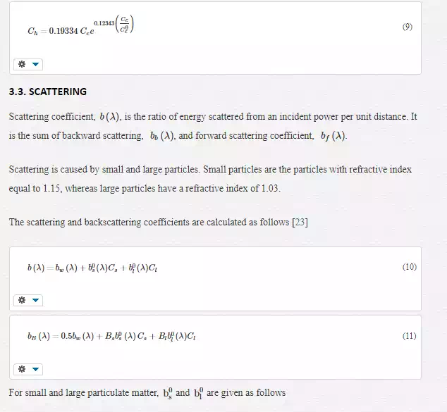
The absorption coefficient, α(λ)α(λ), is the ratio of the absorbed energy from an incident power per unit distance due to various dissolved particles such as phytoplankton, detritus, etc.
OCEANIC TURBULENCE
Optical wireless communications are greatly affected by optical turbulence, which refers to random fluctuations of the refraction index. In the case of underwater systems, these fluctuations are mainly caused by variations in temperature and salinity of the oceanic water.
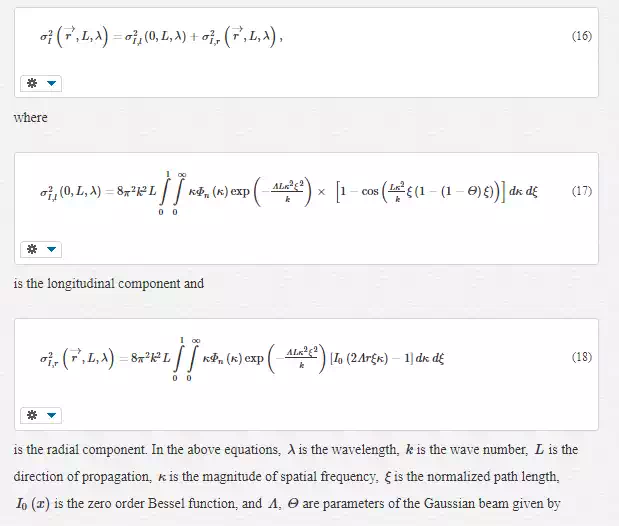
An important parameter for the description of oceanic turbulence is the scintillation index, which expresses the variance of the wave intensity. As shown in Ref. [32], when a Gaussian beam propagates through weak turbulence and without taking into consideration the scattering phenomenon, the scintillation index is expressed as the sum of two components
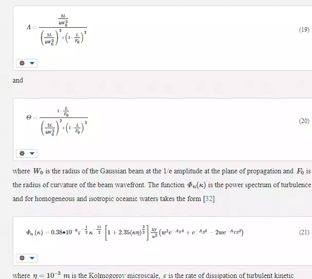
energy per unit mass of fluid, χTχΤ is the rate of dissipation of mean‐square temperature, δ=8.284(κη)4/3+12.978(κη)2δ=8.284(κη)4/3+12.978(κη)2, and ATAT, ASAS, and ATSATS are constants with values AT=1.863×10⁻²AT=1.863×10⁻², AS=1.9×10⁻⁴AS=1.9×10⁻⁴, and ATS=9.41×10⁻³ATS=9.41×10⁻³. The unitless variable ww is the relative strength of the fluctuations caused by either temperature or salinity.
The separation between weak and strong turbulence is usually done via Rytov variance σ2RσR2, which is the scintillation index when a plane wave is considered. More specifically, values of σ2R≪1σR2≪1 correspond to weak fluctuations, whereas σ2R≫1σR2≫1 indicates a strong turbulence regime. In contrast to atmospheric studies, strong oceanic turbulence appears at distances shorter than 100 m [32].
The fading coefficient can be computed statistically using a proper distribution depending on the turbulence regime. As discussed in, the log‐normal distribution is used in situations of weak fluctuations, and its probability density function (PDF) can be written as follows
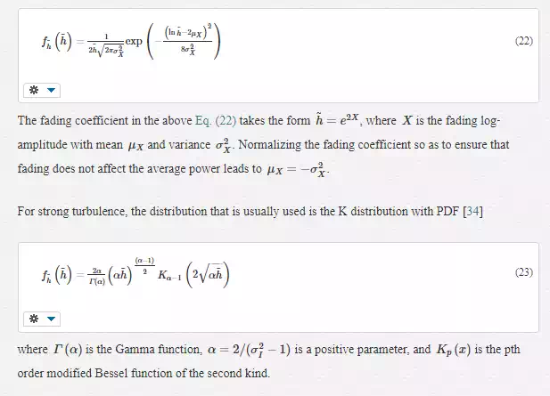
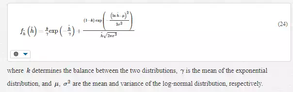
Jamali et al. also proposed the combination of exponential and log‐normal distributions, creating a two‐lobe distribution, to better describe situations of received signals with a large dynamic range. Such a case corresponds to the extensive intensity fluctuations of the received signal, due to the presence of air bubbles. The PDF of this two‐lobe distribution is as follows
Link budget and modulation techniques
LINK BUDGET
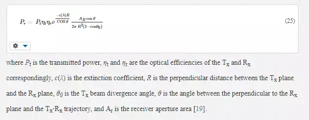
Empirical path loss models are effective enough to estimate the received optical power for underwater communications under LOS conditions. Several models appeared in the literature but the most generic is the following which considers the transmitter power, telescope gain, and losses
OPTICAL MODULATION TECHNIQUES
The most simple and widespread modulation technique is the indirect modulation with direct detection (IM/DD) with on‐off keying (OOK). OOK is divided into two categories, the return to zero (RZ) OOK and the non‐return to zero (NRZ). The expressions for the anticipated bit error rate (BER) are usually produced using the Poisson model for photon arrival in photon counters.
The main disadvantage of OOK modulation is that it requires dynamic thresholding for the direct detection; something not necessary for pulse position modulation (PPM). Here, the transmitter transmits a light pulse and creates a specific time slot, while the receiver detects the pulse, calculates its position, and reforms the signal to the original pulse. PPM consumes lower energy but it has lower bandwidth efficiency. For the L‐PPM scheme, the symbol corresponds to M = log2 L bits. Other modified PPM modulations have been proposed such as differential pulse position modulation (DPPM), dual pulse interval modulation (DPIM), and dual header pulse interval modulation (DH‐PIM).
By exploiting the different polarization states of light, we can improve the performance of UOWC systems in case of intense backscattering, turbulence, and ambient light. Such a way was proposed in, where a binary polarization shift keying (BPolSK) system was employed. Another modulation technique with better numerical results is the polarized PPM (P‐PPM). P‐PPM is a combination of PPM and PolSK and manages to maintain the benefits of both schemes improving data rate, BER, and link distance.
Research on UOWC systems
Research on UOWC is a quite intriguing topic, and several experiments were carried out worldwide. The following are some indicative of the many studies presented in the open technical literature. For more information, the readers are referred to the complete surveys, which examine the UOWC area in more details.
An optical modem capable of optical data mulling was designed and implemented in 2005 at Massachusetts Institute of Technology by Vasilescu et al. They used a LED with 532 nm, 700 mW radiant power and a PIN photodiode receiver with surface area of 8 mm2. They employed DPIM at an average data rate of 320 kb/s with 2 bits per pulse. A 4% packet loss communication over 7 m distance and a close to error‐free over 6.4 m through clear waters was noticed.
Two early versions of AquaOptical, that is, a lightweight device for high rate long range underwater point‐to‐point communication are shown. The researchers used a Luxeon V LED at 470 nm (480 mW) or 532 nm (700 mW) and a PDB‐C156 photodiode in the first version. This is actually a miniaturized version capable of error‐free communication in ocean water at data rates of 4 Mbps over a distance of 2.2 m (470 nm) and 2.4 m (532 nm). In the second one, they employed an array of six such LEDs and an avalanche photodiode, and they managed to achieve a BER of 0.05 at 8 m. The improved AquaOptical II with 18 LEDs and APD at the receiver was demonstrated in 2010. It operated at 470 nm with total transmit power of 10 W. Data rates of 4 Mb/s at 50 m in a swimming pool were achieved using NRZ amplitude modulation with 2 bits per symbol. In a robot estimating its position according to a sensor node in a data mulling application—another usage of Aquaoptical II—was described.
A link budget analysis of NLOS geometries and variations of point‐to‐point links performed in 2005 and 2006 at Woods Hole Oceanographic Institution (Woods Hole MA USA), by Farr et al. Their work is only valid in clear waters because they do not take spatial dispersion and multiple scattering into account even if they consider the attenuation coefficient. Their analysis showed that a LOS link could achieve 10 Mbps at 100 m with 6mW of transmitted power. However, for the NLOS link, a 50‐fold increase in transmit power is necessary to achieve the same data rates at similar range due to broader transmit beams. In 2008, they achieved transmission, at a distance of 200 m for a data rate of 5 Mbps, and in 2010, at a distance of 108 m for a data rate of 10 Mbps.
In 2006, Cochenour et al. used BPSK with a 70‐MHz radiofrequency (RF) carrier at Naval Air Warfare Center to accomplice error‐free communication at a data rate of 1 Mb/s in deep turbid water. Emission wavelength was 532 nm and output power 500 mW. The work was extended in 2007, to 5 Mbps with QPSK, 8‐PSK, 16‐QAM and 32‐QAM modulations and output power 750 mW. Results showed that even in turbid waters (c = 3.0/m and cz = 11), no loss of modulation depth, that is, no temporal dispersion of the 70 MHz carrier was observed, even with a large receiver FOV of approximately 100 degrees. As such, the only channel impairment was due to attenuation. Therefore, with enough optical power (∼3 W), a 32‐QAM link achieved almost 5 Mbps.
Hanson and Radic presented a Monte Carlo model to predict the spreading of an optical pulse for different water types for various FOVs. They managed to improve the signal to noise ratio (SNR) by increasing the FOV for low frequencies. They also observed temporal dispersion at high frequencies. After some manipulations, they eventually achieved 1 GHz transmission over a 2 m water pipe that simulated coastal ocean waters with 36 dB of attenuation. Moreover, Jaruwatanadilok tried to predict temporal dispersion by following the vector radiative transfer theory to model the UOWC channel which includes the multiple scattering effects and polarization. He examined the effect of the transmission distance on channel dispersion and showed a diminishing value of ISI for high data rates over a long distance.
In 2008, Cochenour et al., conducted an analysis of multiple scattering special effects. They measured the beam‐spread function experimentally in a large test tank, by scanning a photodetector laterally to the beam axis after the beam has propagated some distance. Results showed that in clear waters, the intensity falls off rapidly with lateral distance from the beam. However, their estimation ignored any impact of temporal dispersion. In another study on spatial dispersion, they investigated the impact of absorption on forward scattered light. Later the authors also launched a set up which measured the transmission of light modulated at frequencies up to 1 GHz in simulated ocean water up to 55 attenuation lengths. Finally, the authors examined a retro‐reflecting link and managed to reduce the contribution of backscattered light using polarization discrimination techniques.
An experiment conducted in North Carolina State University where a 405 nm laser with OOK was tested in a water tank of 3.66 m long. At first, a reliable transmission at 500 kbps was achieved. Some years later, a duplex communication at 1Mbps was attained. Moreover, Simpson et al. created two separated optical beams of 405 nm with two transmitters and two receivers combined with a beam splitter. In a later work, they presented two set ups, one in 3 m through turbid water and the other over a length of 7.7 m through less turbid water and achieved 5 Mbps throughput.
Dalgleish et al. developed a Monte Carlo simulation method to estimate impulse responses for a particular system hardware design over a large range of environmental conditions in turbid ocean environments. Furthermore, a powerful tool to evaluate the performance of an underwater system for autonomous underwater vehicle communications was presented in Ref. Experimental tests were also carried out. Hardware modules and circuits design for underwater optical point to point links are also discussed in Ref.
NLOS arrangements where optical beams are reflected in the atmosphere‐water interface were discussed in Ref. These geometries have the benefit to avoid occasional obstructions but they do not have the same performance as LOS links. Gabriel et al. assumed a Monte Carlo model of an underwater channel and simulated the trajectories of the emitted photons. They considered several parameters, for example, the transmitter beam width and beam divergence, beam wavelength, link distance, FOV, water types and turbidity, and aperture size. They reached the conclusion that the channel delay spread is nearly zero when the scattering albedo is moderate in small distances.
In the last years, the research is focused on spatial diversity, as a way to improve overall the performance contaminated by turbulence. This is usually accomplished by adding more sources or detectors. Moreover, aperture averaging methods were proposed. In Ref. Yi et al. implemented an aperture averaging technique on the scintillation index for either plane or spherical waves, in order to annihilate the negative effects of fading resulting from oceanic turbulence. A multiple‐input single‐output (MISO) link was described in Ref. where the source is replaced by a uniform circular array of sources, and the photons are collected by a single detector. The numerical results indicated a degradation in BER, under turbulence conditions. A single‐input multiple‐output (SIMO), consisting of a LED as a source and a concentric circular array of lenses as a detector, was discussed in Ref. The system manages to extend the effective communication range by about 20 m, even in the case of strong turbulence. A more general set up of the multiple‐input multiple‐output (MIMO) systems was presented . Finally, in Ref., a spatial diversity technique in combination with optical amplification to further improve performance was proposed.
Conclusions
The need to provide broadband wireless communications for underwater applications will be increasing in the forthcoming years. UOWC constitutes an alternate and effective transmission technique which can attain this scope, instead of the traditional acoustic one. Due to this fact, several studies on UOWC systems were devised worldwide in the recent years. The present study provided a concise review of the key advances in channel modeling and experimental works reported so far in the technical literature.