Analysis of Ambiguity False Fixing within a GBAS[a] -
Paolo Dabove*1 and Ambrogio Manzino*1
[1] Department of Environment, Land and Infrastructure Engineering, Politecnico di Torino – Turin T.U., Italy
Introduction
Since the first appearance of satellite positioning systems, GNSS positioning has become a standard and common practice. It is available in most parts of the territory of many nations. So, it is necessary to focus attention not on the feasibility of the positioning itself but on its quality control. In particular, we focus attention on the NRTK (Network Real Time Kinematic) positioning of a geodetic receiver into a network of permanent stations, the CORS (Continuous Operating Reference Stations) network. The goal of the survey is to obtain a centimetre accuracy, which is usually achieved after a correct fixing of the ambiguity phase. For various reasons, however, it may be possible that the fixing of the integer ambiguities in the receiver can be unreliable. Although the number of false fixes of the ambiguity is limited, it is necessary to minimize these events, or to know some available control parameters needed to alert the user when this eventuality is likely.
The causes of a false fix are mainly a result of four factors:
· inaccurate differential corrections provided by the network;
· unreliable data transmission or high latencies;
· disturbed or partially occluded measurement site;
· electronic or algorithmic problems in the receiver.
Not all of these parameters are controllable or modifiable; some of them can be controlled by the network manager, while others can be controlled by the rover receiver user.
For these purposes, numerous NRTK experiments were performed over many days, using some receivers connected to an antenna settled on an undisturbed site, equidistant from the CORSs stations. Note the position of this station is considered as a ‘false fix’ (hereinafter also called FF) for all the real-time positioning of the rover receiver greater than a tolerance threshold. Later, we analyse the time series of some parameters available in real time (both on the user and network server side) during the NRTK positioning, in order to predict with a significantly high probability what the "most probable" situation for a false fix would be.
The analysis provides an estimator of the ambiguity fixing validity, useful for providing an intuitive and synthetic information for a user during the survey, similar to a "traffic light", and depending on the level of reliability of the solution. Similarly, it is possible to imagine the same architecture transferred to the following inverse logic: if, in fact, the rover receiver transmits the raw data to the network, it is possible to understand more easily if the positions obtained are a false fix or not, and it is therefore possible to notify the user in real time during the survey. In any case, it is then possible to verify whether the false fixes are a result of some quality parameters (and in what percentage) depending on the network in real time, or if they are found in the minimal information that the receiver is able to transmit to the network, contained primarily in the NMEA (National Marine Electronics Association) messages.
Network positioning concepts
Carrier-phase differential positioning has known an enormous evolution owing to phase ambiguity fixing method named ‘On the Fly’ Ambiguity Resolution since 1992 (for example see [7]). Using this technique, a cycle slip recovery, also for moving receivers, was not problematic, but positioning problems, when distances between master and rover exceed 10–15 km, had not yet been resolved. For this reason, at the end of the 1990s, the Network Real Time Kinematic (NRTK) or the Ground-Based Augmentation System (GBAS) was designed, as in [4].
First, to understand the network positioning concept, it is necessary to keep in mind some concepts about differential positioning. To do this, it is possible to write the carrier phase equation in units of length:

After that, double differences equations can be written considering two receivers (h and k) and two satellites (p and q). By subtracting the single difference calculated for the satellite q from the one calculated for the satellite p, it is possible to obtain the double differences equation, neglecting the random errors contribution:

When the distance between the two receivers is lower than 10 km, the atmospheric propagation delays and the ephemeris errors are irrelevant, allowing centimetric level of accuracy. Over this distance, these errors increase and cannot be neglected. Otherwise, these errors are spatially correlated and can be spatially modelled (as possible to see in [5]). However, to be able to predict and use these biases in real time, three conditions must be satisfied: the knowledge of a centimetric accuracy of the master positions; a control centre able to process data from all the stations in real-time; and the continuous carrier-phase ambiguity fixing, even when interstation distances reach 80–100 km. (This last condition in the control centre network software is called “common ambiguity level fixing”). This concept is equal to bring to the left-hand side of (3), among the known terms, the first two terms on the right-hand side, i.e.:

If the software uses the first differences, or undifferenced phase equations, in the first case, it is essential to calculate and model the clock errors of the receivers and, in the second case, also those of the satellites, in addition to a series of secondary biases that are usually not considered in differencing techniques. After the phase ambiguity fixing for all the network stations, it is possible to use the iono-free and geometry-free combinations to separate the ionospheric delay by the geometric one. In this way, having these biases for all the stations, it is possible to model the residual ionospheric and tropospheric biases and the ephemeris error, not only between stations h and k, but also among all the reference stations of the network. When these errors are modelled spatially, they can be interpolated and broadcast to any rover receiver.
The differential corrections will no longer be broadcast by a single master station, but by the network centre. It is not always necessary for the network software to send the interpolated biases to the rover receiver. Once the dispersive (
αiIpqhkαiIhkpq
) and non-dispersive (
Tpqhk+EpqhkThkpq+Ehkpq
) biases for each station and each satellite have been estimated, it is possible to follow three paths:
· to transmit data from one network station (called the master station), together with the first differences of a few stations, called "auxiliary” stations, close to the rover receiver (Master Auxiliary Concepts - MAC mode);
· to model these biases within the area of the network and transmit the parameters of this model (Flächen Korrektur Parameter - FKP mode);
· to interpolate these data close to the rover receiver and build some synthetic data for this receiver as if they were generated by a station very close to the receiver. (Virtual Reference Station - VRS®mode).
In MAC mode, the receiver's task is to use data provided by a master station and the first differences of some auxiliary stations. It can then perform a multi-base position and the biases can be interpolated as necessary. The amount of data and calculations that the rover receiver can do is considerable. On the other hand, the multi-base positioning can be much more accurate than other methods. Finally, the user chooses the best way to use the data in a subnet. The NRTK network must only carry out the ambiguity fixing and transmit MAC corrections. Inside this cell the same correction is identical for all rover receivers and could also be transmitted by radio.
In the FKP method, the network software models the geometric parameters and dispersive biases over a wide area. Subsequently, the data derived from a master station and the parameters of this model are transmitted to the rover. The “one-way” approach for this type of correction could also be used in this case. Compared to the MAC method, the network software must also model the biases in the area of the network correctly.
Considering the VRS® positioning, the task of the network software is not only to model, but also to interpolate these biases, close to the position of the receiver that "sees" these corrections as if they came from a master station that actually exists. The task of the network software increases and decreases that of the receiver (as possible to see [1]).
In all three cases, it is necessary to control the quality of the positioning, both from the side of what provides the network, and from how the generic network product is used by the rover receiver. The quality of the positioning is a parameter that must be monitored in real time to avoid a wrong phase ambiguity fixing happening (also called "false fixing": FF). Often this is a result of internal problems of the network software or, more often, the poor quality of the environment in which the rover receiver works.
Strategy for the control of the NRTK fixing
To achieve this control, a tool was designed that, starting from the data available in real time by a user connected to an NRTK positioning service, can identify with a certain probability threshold (the calibration on this tool depending on the type of receiver available) the effective presence, or the possibility of a false fixing in the position. The input data of this instrument (hereinafter referred to as the "FF Estimator") will be the real-time data available from the NMEA message, extractable from the rover receiver (number of satellites in view, Diluition Of Precision – DOP - index, delay of the differential correction), and those which may be obtainable by the network software (typically, the tropospheric and ionospheric delay, the number of satellites fixed by the network, the network quality fixing).

The FF estimator will be composed of a neural network, trained a priori with some datasets, and will have, as a single output, the probability that the current fixing is a false fixing of the ambiguity of phase. In this regard, it will be necessary to identify, among all available data in real time, those most sensitive both to the deterioration of the accuracy and the presence of the false fixing. These parameters will be those used to calibrate ("train") the neural network. Downstream of the estimator, a representative index is provided as an output of the algorithm (shown schematically in Figure 1 by a traffic light), of the quality of the fixing, possibly allowing the user to re-initialize the measurement session. The change over time of these probabilities is useful to forecast an incorrect positioning (not always considered as a false fix) before it actually occurs.
Notes on neural network
Artificial neural networks are informatic tools that simulate the connections of neurons in the human brain, and are used to make decisions, approximate a function, or classify data. In our case, the function or the decision is to assess the probability of a false fixing, and provide as output an indicator simulating the behaviour of a traffic light, allowing the user to have visual and intuitive information about the quality of the coordinates of the NRTK survey, available in real time.
Neural networks are made up of n nodes, called artificial neurons, connected to each other, which, in turn, are ordered in layers. There is one input layer consisting of a limited number of neurons, one output layer (in our case constituted by a single neuron that represents the decision on the false fixing), and one or more intermediate layers. Each neuron communicates with one or more neurons in a subsequent layer. The first layer receives information from the input and returns it in the next layer through interconnections. The connections between one layer and the next do not transmit the output values derived from the previous layer directly, but transmit weighted values through weights wij that are assigned to each of these connections. These weights are the unknowns of the problem; to calculate them it is necessary to "train" the network. In other words, it is necessary to perform a training phase which is based on providing, as input, a set of data for which you know the result in output. On each neuron of a layer the weighed contributions of neurons of the previous layers and a generally constant bias value are summed into the input. A function is applied at this sum and the result is the output value from that neuron (for example see [6]).
As mentioned above, it is necessary to provide a training phase of the neural network; there are essentially three ways: an unsupervised learning, one called reinforcement learning and one supervised learning. The first method (unsupervised) allows to change the weights considering only the input data, trying to evaluate in the data a certain number of clusters with similar characteristics. The second method (reinforcement) follows a supervised strategy but it can be adjusted depending on the response of the external application of the parameters obtained. The last mentioned mode (supervised) is used when, as in the present case, a dataset is available (called the training set) for a training phase. The algorithm of supervised learning implemented is the so-called "backpropagation", which uses both the data provided by the input and the known results in output, to modify the weights so as to minimize the prediction error called network performance (goal function). In the cases in this work, we need to minimize the mean square error:

where OiOi is the neuron output of the last level and TiTi is the known value that we want. This process is iterative: the first iteration of the associated weights between neurons of two adjacent layers have values small and random, which are then updated at subsequent iterations. There are two ways to implement the training: the incremental mode; and the batch mode. In the first, the weights are updated after each input is applied to the network. In the second, all the inputs in the training set are applied to the network before the weights are updated (for example see [8]). To do this it is possible to use the gradient of the network performance compared to the weights, or the Jacobian of the network errors (Ti−Oi)(Ti−Oi) with respect to the weights. Gradient or Jacobian are calculated using the "backpropagation" technique, which gets the values of the weights by using the chain rule of calculus. The training algorithm used in these application is the Matlab® routine “trainlm”, based on Levenberg-Marquardt optimization. The training phase occurs in two distinct phases, called the forward pass and the backward pass,respectively. The first phase allows both to derive the estimation error between the input data (applied to the input nodes) and the results obtained in output (which are known), and to propagate this error in the reverse direction, while in the second phase, the weights are modified in order to minimize the difference between the real and the known, desired output.
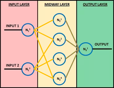
In Figure 2, the generic neuron k of the j-th layer is indicated by NkjNjk. Neurons with subscript 1 are the input neurons, whose number must be greater than or equal to the number of input. The input value I, for a generic neuron j of the k-th layer which is not of the first level, is therefore given by

where l represents the number of neurons of the previous layer, whwh the weights of these neurons, and bkbk the value of the bias. So for each neuron that is not at the first level, the inputs of the layer above, weighted with weights ww, are summed, adding a further bias bb. The neurons process the input through a certain function called transfer function: of all the transfer functions, the Hard Limit, the Linear and Log Sigmoid are the best known (Figure 3). In addition to the transition function, each neuron is characterized by a threshold value. The threshold is the minimum value that must be present in input that allows the neuron to send something in output and is, therefore, active. Beyond this threshold value the neuron transmits a value to the next layer that is the result of the application of the transfer function

Generally, between one level and the next, all the neurons of the first level are connected with all the neurons of the second. It should be emphasized that there are neural networks in which there are also connections between neurons of the same level, but this does not happen in the case presented in this chapter. After the training phase, the effectiveness of the network is tested on a new set of data, called the test set. This set of data must be constituted by values of input and output never seen by the network. If the results offered by the network are close to the actual values, then the network can be considered valid. In these cases, it is said that the network is effective in generalization.

The neural network used in these experiments is shown schematically in Figure 4. The input consists of three vectors which are, for all epochs, the values of the HDOP (Horizontal Diluition Of Precision) index, the latency of the correction, and the number of fix satellites seen by the rover. The training set is constituted, for every epoch, by a Boolean vector consisting of 1, in the case of a false fix, and 0 otherwise. The hidden layer consists of three neurons. The transfer function in the hidden layer is the Log-Sigmoid, while the layer is linear for output. The training function used is (always) the Levenberg-Marquardt backpropagation Algorithm.
The dataset for training the network was divided as follows: 50% training; 30% validation; 20% testing. As mentioned, the control of what causes a FF is executed simultaneously in two respects: the verification of what is happening on the network at the time of the FF; and the control of what the user can see on the rover receiver. The quality parameters, reported and considered significant to identify the reason for the FF, are extended for a period before and after the false fixing, established at five-minute intervals (300 s). Almost always this period, especially before the false fixing, is sufficient to understand what is injuring the positioning.
Analysis of the quality parameters
QUALITY PARAMETERS OF THE NRTK NETWORK
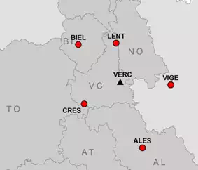
Before testing the developed algorithm, it was necessary to choose the network architecture to support the measures. We chose the Geo++ GNSMART ™[1] - http://www.geopp.de/index.php?sprachauswahl=en&bereich=0&kategorie=31&artikel=35 software as the network software of permanent stations because it allows the user to extract information on the real-time calculation of the network: it is possible to have the state vector of the network calculation as an output, every 15 seconds. This information is transmitted to the server, in an ASCII format, and links the age of the false fix with a network event that may cause estimation problems for the rover receiver. Within the software GNSMART (version 1.4.0) a network of five stations was therefore set up, settled around the measurement site and having an inter-station distance of about 50 km. This type of configuration allows the simulatation of meshes of today’s typical positioning services, and was therefore considered to be representative of the tests performed.
The permanent stations involved in these tests are shown in Figure 5 and detailed in Table 1


The reference coordinates of the stations were obtained by adjusting 15 days of data with the Bernese GPS software (v. 5.0), in the reference system IGS05, constraining the coordinates with the 5 closer IGS (International GNSS Service) stations.
As mentioned, the control of what causes a FF is executed simultaneously in two respects: the verification of what is happening on the network at the time of the FF; and the control of what the user can see on the rover receiver. Therefore, by combining the network information with the information of the receiver, a reliable decision is more likely to be reached, regarding the measurement period. The association has been possible thanks to the GPS time scale in both files: the one produced by the receiver in NMEA message; and the one produced by the network. Thereafter, for predicting the quality of the NRTK positioning, a software was developed that does not yet use the information derived from the network, but is already suitable to process these parameters. Before using any software that automatically predicts a quality index of positioning, it was necessary to analyse which parameters are more sensitive to the fixing degradation when observing the network status parameters. Since the state vector, which is obtained as output from the network, is complete, it should be noted that much of the information is not essential for checking the quality of the network data. It was therefore necessary to make a decision. The following are considered to be the only useful parameters:
· Number of GPS and GLONASS (GLObal'naya NAvigatsionnaya Sputnikovaya Sistema) satellites seen by the network stations for each age. In particular, it was decided to plot the minimum number among all satellites viewed from the stations of the network.
· Number of GPS and GLONASS satellites fixed by the network for each age.
· rms (root mean square) of the carrier phases compensation obtained in the current epoch, expressed in metres (σep).
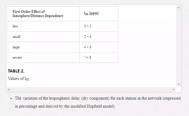
· The value of the ionospheric delay expressed in ppm along the vertical direction. This index, that is a characteristic value of the GNSMART software, is called I95 and is indicative of the error obtained from the global estimation of the ionosphere (for example see [3]):
THE QUALITY PARAMETERS AVAILABLE AT THE ROVER RECEIVER
The station, which for several days simulated a rover receiver, was a receiver placed in the Geomatics Laboratory at Vercelli; this receiver was connected with a geodetic antenna settled on the roof of the same laboratory (Figure 6). The coordinates of that station were calculated in the same network frame of reference system, through a post-processing approach of 24 hours of data with the nearest station (LENT).
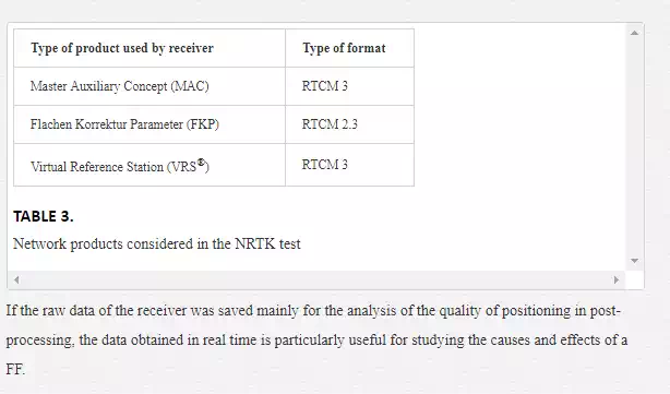
For each network product used (FKP, MAC, VRS) (Table 3) and for each geodetic instrument, RTK positioning with 24 hours of session length were performed, with an acquisition rate of 1 s, in order to obtain results that were independent of the constellation view from the GNSS receiver. This chapter will show the results of a receiver which we believe has shown representative average behaviour with respect to all the receivers used. For each network product, both the raw data and the real time positions were saved: the last one is obtained through the GGA field of the NMEA message, transmitted via a serial port to a computer close to the receiver in the acquisition.
If the raw data of the receiver was saved mainly for the analysis of the quality of positioning in post-processing, the data obtained in real time is particularly useful for studying the causes and effects of a FF.
From the NMEA message sent by the receiver we extracted the following information:
· mean square error (rms) of the position, calculated on the 30 s before the current epoch;
· rms of ellipsoidal height, also calculated 30 s before the current epoch;
· the age of differential correction broadcast;
· number of satellites received;
· HDOP (Horizontal Dilution of Precision) index.
SEARCH OF THE DIFFERENT TYPES OF FF AND ITS RELATED PARAMETERS
To try and assess any FF occurred during the measurement phase, the reference coordinates were compared with those obtained in the NRTK survey by the rover receiver, considering only the "fix" coordinates, where “fix” means that the ambiguity value of the carrier phase measurements were fixed to the integer correct value. As already mentioned, several geodetic receivers were tested, as well as different types of network products. Not all results are shown, but the idea here is to present the most significant ones. Another threshold was considered: the limit of acceptability of the three-dimensional error in 20 cm was established, in order to assess whether or not the event is a FF. This value is fairly generous and was chosen as corresponding approximately to a wavelength of the carrier phase L1. Three-dimensional errors less than 20 cm do not necessarily correspond to epochs where the phase ambiguity is fixed in the correct way: FFs may exist for which the positioning errors are much lower than 20 cm. However, an ambiguity fixing that shows a three-dimensional error (i.e. the difference between the "true" position and the measured one) of more than 20 cm is definitely a false fix. Another threshold is the minimum length of the false fix (i.e. the minimum time necessary to be considered is significantly dangerous). This limit is imposed as equal to 5 seconds, because FFs with a lower length are too short to be considered deleterious. It is possible to think now not a mobile positioning, but at a NRTK "stop & go" survey. In this hypothesis, it is expected that the surveyor acquire a point for more than 5 seconds and perform the average of the coordinates obtained, thus easily identifying the measure that causes the false fixing. This option can certainly be removed or modified in the choice of the FF, and during the training of the neural network.
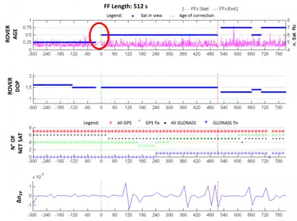
The following graphs show both the network and receiver parameters that can justify and provide a false fix in some way. Two vertical stripes in green and red denotes the beginning and the end of FF. For each case of FF, a series of graphs is shown, showing the values described above in a common time scale for the network and the receiver. All analysis concern the analysis of the behaviour network-receiver within 24 hours length of RTK measurements. Considering the network shown in Figure 5, during the tests with VRS®, FKP and MAC corrections, it 21 false fixes were identified with a time length between 6 s and 1136 s (corresponding to 18 minutes). Many of these have a similar typology, and for that reason not all the false fixes mentioned before are reported here, only the three main types. We will now examine three emblematic cases of FF.
TYPOLOGY OF FF NO. 1: LATENCY DEPENDENT
The first typology involves the FF identified using the MAC product. It is possible to see the graphs relating to the variation of Δ3D three-dimensional error (related to the E, N and h coordinates), and the elevation error Δh, with the respective standard deviations. It was decided not to show the graphical error related to the coordinates E and N because it is insignificant if compared to those previously mentioned. It is common for the more significant error to be the altimeter one, and there isn’t a preferred direction in the planimetric one.
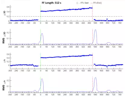
By
analysing the first FF and considering a time interval of five minutes, it is
possible to see a similar trend in the latency of the correction (Figure 8). Note that the receiver does not receive
data for a period of time of a few seconds. The DOP index registered by the
receiver is kept fairly constant; there are, in fact, only "steps"
corresponding with variations in the number of received satellites. 150 s after
the start of the FF the number of these satellites decreases below the minimum
available for the positioning. It is possible that one of the four satellites
corrected by the network has not been available to the receiver. It is also
possible to see the graph containing the value of the root mean square σ
registered by the receiver. It can be seen how this magnitude does not reveal
any particular problems before or during the FF, with a trend without excessive
anomalies.
The values of the ionosphere and troposphere are also considered, related to the variation of the CORS station constituting the network. Such information, which is not shown, have been extracted from the state vector of GNSMART, as described in the introductory part of the present work. In both cases, we do not obtain significant changes of the values at the beginning of the FF, while it has the presence of a peak of both ionospheric and tropospheric delay at the half of the same, which corresponds to the fixing of only three satellites by the network. The presence of the peak of the troposphere is also justified as an "attempt" by the network software to restore the correct behaviour in the biases estimation. The low number of corrected satellites compared to those seen by the receiver may be a temporary problem of the network software.
TYPOLOGY OF FF NO. 2: WRONG IONOSPHERIC NETWORK ESTIMATION
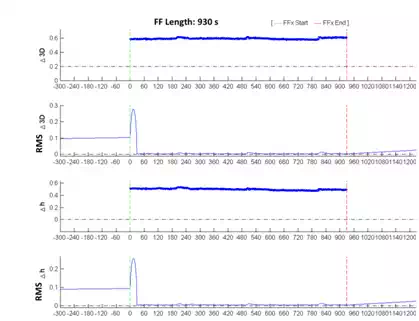
This type of false fixing is unusual because there is no data before or after the FF: the first positioning with the ambiguity fixed, which occurred only 5 seconds after the switching on of the instrument, is already incorrect. The following graphs, relating to the 3D and elevation errors, show the presence of values only in correspondence to the FF error values in the order approximately of 50-60 cm, that are much higher with respect to the threshold set equal to 20 cm (Figure 9). At the beginning of the false fix, however, the rms of the position rises up to 30 cm before becoming very low.
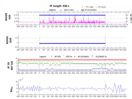
The graphs in Figure 10 do not show meaningful behaviour which can be attributed as the cause of the false fix. In fact, the latency of the correction is lower in magnitude than what is already found. The DOP index remains constant as the number of satellites seen by the receiver is also constant, while the number of satellites seen, and with ambiguity fixed by the network, increases (both GPS and GLONASS). Finally, the variation of the σ value is not significant during the FF, only before. There is, on the other hand, a quite significant variation in the ionospheric and tropospheric delays (the latter especially after the end of the FF, probably corresponding to the intention of restoring, using the network software, a more correct, common level of ambiguity fixing. This is shown in Figure 11).
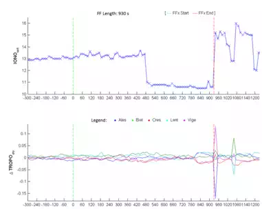
Probably, there is also a network problem even 300 seconds before the false fixing. It isn’t possible that, 450 seconds after the FF, there is a variation of more than 3 metres in the ionosphere.
TYPOLOGY OF FF NO. 3: HIGH DOP INDEX VARIATION
This typology represents the false fix with the longer length, similar to type 2 with the lack of data before and after the FF, but it comes back to fixing the ambiguities around the epoch 1,300.
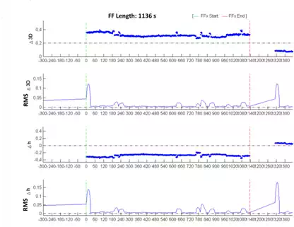
As seen in Figure 12, the rms of coordinates increases and exceeds the first decimeter before the FF. It is possible to know, unlike the other cases, that the value of the ionospheric delay during the FF decreases suddenly, unlike that of the tropospheric one which has a fairly constant trend (Figure 14). The DOP values, while being low at the beginning of the FF, rise after about 90 seconds, with values greater than or equal to 2, and decreasing to reasonably low values around the epoch 1300 (Figure 13).
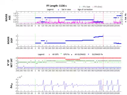
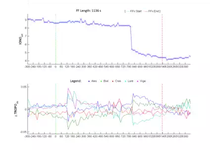
Despite the existence of a FF where it is not possible to identify the main trigger, it is however possible to affirm that the significant values that enable the presence of a false fix to be identified with high probability are:
· the latency of the correction;
· the noise level of the σ value of the coordinates on the receiver;
· the DOP index and then the parallel number of satellites used (parameters that can be separated);
· the variations of the ionospheric and tropospheric biases computed by the network software.
These parameters are visible from both the receiver (points 1, 2, 3) and the network (point 4). Some of them are usually transmitted to the network software with the NMEA message, in the case of a bidirectional exchange of information. With this message, the network software is able to evaluate the state of the receiver (fixing or not).
Some analysis was carried out in real time using CORS networks with larger extension (inter-station distances of about 100 and 150 km), but the results are omitted because, with these networks, the number of FFs obtained is amplified with respect to the network presented (without changing the typology), with an inter-station distances of about 50 km [1]. This deterioration is clearly linked to a growing difficulty in the interpolation of the corrections by the network if the inter-station distances increase.
Implementation and results of the neural network
After the analysis of the types of false fix and the main factors that determine the occurrence of an incorrect fix, it was decided to develop a neural network to predict the wrong fix of the ambiguity phase. To do this, a "neural network" toolbox, available in the Matlab® computer program, was used. Particular attention was devoted to the training phase: it is of fundamental importance to "train" the network correctly, in such a manner that it is able to predict, after this phase, the possible false fixing of the ambiguity. Four different methods were tested, depending both on the type of the input training file (each file was composed by 3 days of observations), and the number of neurons considered in the hidden layer:
· Net1: the network is composed of 3 neurons; the training file derives from a real data file of 24 hours’ length (containing of about 15 FF);
· Net2: the network is composed of 3 neurons; the training file is a file prepared ad hoc (in terms of data densification and order of FF typologies, such as FF due to latency, DOP index and number of satellites, hereafter called man-made) containing about 15 FFs, owing mainly to latency correction and sudden variation in the number of satellites;
· Net3: the network is composed of 10 neurons; the training file derives from a real data file of 24 hours’ length (containing about 15 FFs also in this case);
· Net4: the network is composed of 10 neurons; the training file is a man-made file containing about 15 FFs, owing mainly to latency correction and sudden variation in the number of satellites.
To understand which types of previous network obtain the best performances, an additional day (session length of 86400 epochs) of independent measurements was used. The results obtained are shown in Figure 15.
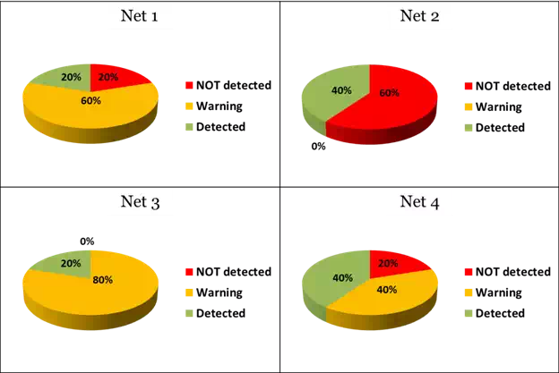
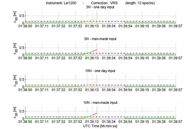
It is possible to see how Net3 is the network that identifies all the FFs, declaring 20% as certain FFs while 80% are defined as possible FFs (hereinafter called also warning). The other networks have worse behaviour, not identifying 20% or 60% of false fixings occurring in the day used for the test phase. More specifically, and choosing a randomly FF that occurred on that day, it is possible to see that even in this case (Figure 16) Net3 predicted a FF about 5 seconds in advance. Other networks, such as Net2 or Net4, not only did not identify it, but also noticed of the event only after that it had started.
Therefore, considering Net3 as the best trained and available neural network, some tests with a session length of more than 72 hours (3 days) were carried out, in order to test the trained neural network on new data, acquired from different receivers of the main companies operating in the market. The results only show of a dual frequency and dual constellation receiver, chosen as representative (called a "medium receiver"), in terms of behaviour and quality of positioning. The information contained in the GGA field of the NMEA message was analysed, considering only the epochs with a fixed ambiguity phase. Even for these experiments it was considered to be a static survey with the rover instrument mentioned above, located in Vercelli (Figure 6), the CORSs network as described above (Figure 5), and only VRS® and MAC corrections.
Table 4 shows the number of FFs obtained by considering the two different corrections and three different sessions of measurement (each of which, as previously mentioned, with a duration of 72 hours). It may be noted first that, with the VRS® correction, a smaller number of false fixes is obtained generally. It should be emphasized that the experiments were not performed considering the two corrections simultaneously, but the choice of using such a big survey time window allows us to affirm that there is no dependence on the geometry of the satellite constellation, or on external factors.
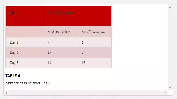
By means of a special program, developed in Matlab®, it was possible to analyse all those epochs when the estimated position differs by at least 20 cm (considered as certain FF because it is a static survey) from the “correct” one. It was also possible to create some statistics results, not on the quality of positioning but on the ability to predict and identify a FF in real time. We will analyse only two cases, considered significant, and chosen from among all the sessions, analysed during the training phase: the "best case", which represents the session in which the network predicted the maximum number of FFs, indicating them as a warning or as a red alert (epochs declared as a certain FF), and the so-called "worst case", when the network predicted the minimum number of FFs.
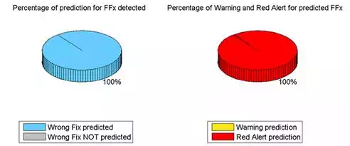
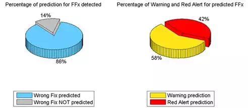
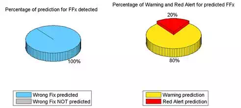
Some statistics on the stability of the ambiguity fixing were also carried out, and considered the length (in seconds) of the phase ambiguity fixing, but they are not reported in this paper. Figure 17 and 18show the two extreme cases of prediction and detection of FF considering the MAC correction. It is possible to see how, in the "worst case", 86% of the false fixes are identified (about 9 out of 10 FFs), of which 42% are declared as certain. In the "best case" it is possible to see how all the FFs are detected, and 20% of these are declared as certain FFs. It should be emphasized that there is no cause for concern owing to a low rate of false fixes declared as certain: it is important that they are identified as even possible FFs (warning) rather than they are not identified at all. Considering the possibility of reporting the quality of the positioning to the user during the survey, and comparing the quality of the survey using a traffic light sysytem, the epochs when the neural network does not show any abnormality could be identified by a green light, the epochs when there is a warning by a yellow light, and when the FF is declared as certain (red alert) by a red light.
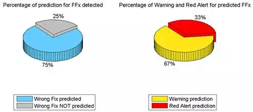
If we consider instead the VRS® correction, it can be seen that in the "worst case", 25% of FFs are not predicted. This percentage is quite worrying as it means that 1 in 4 FFs could not be identified. Of the remaining 75% of predicted FFs, 33% (or rather 1 in 3) are declared as a certain false fix, while 67% are a possible false fix (warning). Another important analysis regards the percentage of "errors" of the neural network, in terms of the number of sure or possible FF that there are not been verified.
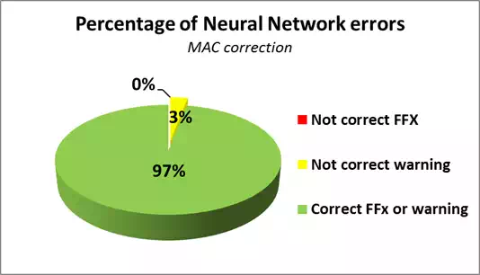
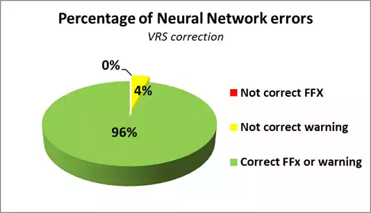
As can be seen from Figure 21 and 22, the neural network can be considered efficient, considering the MAC and VRS® corrections respectively, because 3% and 4% of cases report possible FFs that do not really occur, while never sure FF happen. So it is possible to affirm that the type of neural network and its training phase have proved effective. In this phase of the job, we only considered a few parameters obtained from the NMEA message, ignoring all the information derived from the network software that could further improve the results. We, therefore, want to continue in the future, to carry out experiments to try and reduce the 25% of unpredicted FFs that occur, and that cannot be identified by the parameters considered in the current state and, as shown in the graphs, reveal almost certainly a problem in a NRTK network.
Conclusion and future developments
As shown in the present work, it is not always possible to identify which parameter (or its variation) leads to a false fix. It is, however, possible to affirm that, according to the studies carried out, the significant quantities that allow the receiver to identify the presence of a FF with high probability, are:
· the noise of the rms value (σ) of the three coordinates;
· the DOP index and therefore the number of satellites used in parallel.
It appears, in the authors’ personal opinion, to be of great importance to consider the network parameters (such as ionospheric and tropospheric delays), to try to identify the triggers of FFs — currently unexplained by only considering the parameters — to attempt to reduce quite high rates of unreported false fixings. It should, however, be underlined again that a low rate of FF declared as certain is not a cause for concern. It is important that they are identified even as a possible FF (warning) rather than not be identified.
The input parameters of the network can be expanded. In addition, it is possible to affirm that the network can be trained for a "stop & go" positioning of the rover receiver or, with proper choice of these parameters, for a receiver in motion. The user will choose the type of survey and the receiver and, at the same time, the type of quality control of the survey.
For a quality analysis of the survey to be made in retrospect, it might be important to combine visual information (colour) with the quality of the measurements. For example, it might classify these measures on a screen indicating these points and the respective colour code (from green for the measures considered reliable, up to red for the measures considered unreliable), so the user can later return to measure, perhaps with other conditions of the satellite visibility, the points made previously little or not reliable.
[1] - For more details visit the webpage:
