Designing Convergent-divergent Nozzles
With our new-found knowledge on supersonic flow and nozzles we can now begin to intuitively design a convergent-divergent nozzle to be used on a rocket. Consider two reservoirs connected by a convergent-divergent nozzle (see figure below).
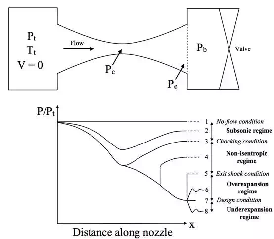
Convergent-divergent nozzle schematic and variations of pressure along the length of the nozzle
The gas within the
upstream reservoir is stagnant at a specific stagnation temperature ![]() and
pressure
and
pressure ![]() . The pressure
in the downstream reservoir, called the back pressure
. The pressure
in the downstream reservoir, called the back pressure ![]() , can be
regulated using a valve. The pressure at the exit plane of the divergent
section of the nozzle is known as the exit pressure
, can be
regulated using a valve. The pressure at the exit plane of the divergent
section of the nozzle is known as the exit pressure ![]() , and the
pressure at the point of minimum area within the nozzle is known as the throat
pressure
, and the
pressure at the point of minimum area within the nozzle is known as the throat
pressure ![]() . Changing
the back pressure
. Changing
the back pressure ![]() influences the variation of the pressure throughout the
nozzle as shown in the figure above. Depending on the back pressure, eight
different conditions are possible at the exit plane.
influences the variation of the pressure throughout the
nozzle as shown in the figure above. Depending on the back pressure, eight
different conditions are possible at the exit plane.
1.
The no-flow condition: In this case the valve is closed and ![]() . This is the trivial condition where nothing interesting happens.
No flow, nothing, boring.
. This is the trivial condition where nothing interesting happens.
No flow, nothing, boring.
2.
Subsonic flow regime: The valve is opened slightly and the flow is entirely subsonic
throughout the entire nozzle. The pressure decreases from the stagnant
condition in the upstream reservoir to a minimum at the throat, but because the
flow does not reach the critical pressure ratio ![]() , the flow does not reach Mach 1 at the throat. Hence, the flow
cannot accelerate further in the divergent section and slows down again,
thereby increasing the pressure. The exit pressure
, the flow does not reach Mach 1 at the throat. Hence, the flow
cannot accelerate further in the divergent section and slows down again,
thereby increasing the pressure. The exit pressure ![]() is
exactly equal to the back pressure.
is
exactly equal to the back pressure.
3.
Choking condition: The back pressure has now reached a critical condition and
is low enough for the flow to reach Mach 1 at the throat. Hence, ![]() . However, the exit flow pressure is still equal to the back
pressure (
. However, the exit flow pressure is still equal to the back
pressure (![]() ) and therefore the divergent section of the nozzle still acts as
a diffuser; the flow does not go supersonic. However, as the flow can not go
faster than Mach 1 at the throat, the maximum mass flow rate has been achieved
and the nozzle is now choked.
) and therefore the divergent section of the nozzle still acts as
a diffuser; the flow does not go supersonic. However, as the flow can not go
faster than Mach 1 at the throat, the maximum mass flow rate has been achieved
and the nozzle is now choked.
4.
Non-isentropic flow regime: Lowering the back pressure further means that the flow now
reaches Mach 1 at the throat and can then accelerate to supersonic speeds
within the divergent portion of the nozzle. The flow in the convergent section
of the nozzle remains the same as in condition 3) as the nozzle is choked. Due
to the supersonic flow, a shock wave forms within the divergent section turning
the flow from supersonic into subsonic. Downstream of the shock the divergent
nozzle now diffuses the flow further to equalise the back pressure and exit
pressure (![]() ). The lower the back pressure is decreased, the further the shock
wave travels downstream towards the exit plane, increasing the severity of the
shock at the same time. The location of the shock wave within the divergent
section will always be such as to equalise the exit and back pressures.
). The lower the back pressure is decreased, the further the shock
wave travels downstream towards the exit plane, increasing the severity of the
shock at the same time. The location of the shock wave within the divergent
section will always be such as to equalise the exit and back pressures.
5.
Exit plane shock condition: This is the limiting condition where the shock wave in the
divergent portion has moved exactly to the exit plane. At the exit of the
nozzle there is an abrupt increase in pressure at the exit plane and therefore
the exit plane pressure and back pressure are still the same (![]() ).
).
6. Overexpansion flow regime: The back pressure is now low enough that the flow is subsonic throughout the convergent portion of the nozzle, sonic at the throat and supersonic throughout the entire divergent portion. This means that the exit pressure is now lower than the gas pressure (the flow is overexpanded), causing it to suddenly contract once it exits the nozzle. These sudden compressions cause nonisentropic oblique pressure waves which cannot be modelled using the simple 1D flow assumptions we have made here.
7. Nozzle design condition: At the nozzle design condition the back pressure is low enough to match the pressure of the supersonic flow at the exit plane. Hence, the flow is entirely isentropic within the nozzle and inside the downstream reservoir. As described in a previous post on rocketry, this is the ideal operating condition for a nozzle in terms of efficiency.
8. Underexpansion flow regime: Contrary to the over expansion regime, the back pressure is now lower than the exit pressure of the supersonic flow, such that the exit flow must expand to equilibrate with the reservoir pressure. In this case, the flow is again governed by oblique pressure waves, which this time expand outward rather than contract inward.
Thus, as we have seen the flow inside and outside of the nozzle is driven by the back pressure and by the requirement of the exit pressure and back pressure to equilibrate once the flow exits the nozzle. In some cases this occurs as a result of shocks inside the nozzle and in others as a result of pressure waves outside. In terms of the structural mechanics of the nozzle, we obviously do not want shock to occur inside the nozzle in case this damages the structural integrity. Ideally, we would want to operate a rocket nozzle at the design condition, but as the atmospheric pressure changes throughout a flight into space, a rocket nozzle is typically overexpanded at take-off and underexpanded in space. To account for this, variable area nozzles and other clever ideas have been proposed to operate as close as possible to the design condition.