Airfield
The airfield is marked with a variety of signs delineating the taxiways, stoplines, holding areas, and the like. Blue lights indicate taxiway edges. Stop bars before crossing or entering an active runway are yellow. There have been a number of accidents and near accidents on the ground, especially when the visibility is low. The FAA is experimenting with a new lighted stop bar. The controller controls the lights. When the bar is lit there are now center lights ahead, creating a black hole effect. Once the aircraft is permitted on the runway, the light bar is extinguished and the taxiway/runway lights are illuminated to guide the pilot onto the runway for takeoff [FAA, 1993b]. Typical airfield markings give the pilot directions to the ramp, parking areas, fuel, gates, areas for itinerant aircraft, ramps for military aircraft, cargo terminals, international terminals, and other airside functions. Visual cues also aid the pilot in docking the aircraft at the gate.
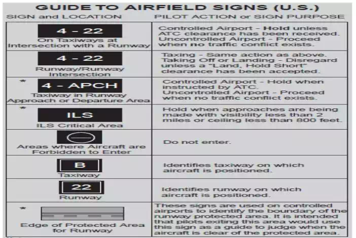
Generally there is also an airline ground employee with handheld signal lights to direct the pilot as the aircraft pulls into the gate. Figure 5.12 shows the FAA’s 1993 guide to airfield signs.
Approach to the Runway The approach lighting system (ALS) dictates the navigation and approach capability. Light bars may extend as much as 3000 feet from the threshold along the aircraft’s desired glide path. Lighting systems are available to provide runway glide slope cues indicating whether the pilot is above, below, right, or left of the hypothetical wire representing the proper descent trajectory. The visual approach slope indicator systems (VASIS) provide at the side of the runway red and white light bars. The precision approach path indicator (PAPI) system provides upper and lower lights of red and white that in various combinations indicate whether the pilot is too low or too high. For example, an all-white bar indicates the aircraft is on a glide slope greater than 3.5 degrees, while an all-red bar is less than 2.5 degrees. Equal red and white indicates the aircraft is on the 3-degree glide slope. Positioning along the glide path is accomplished by the use of light bars extending from the runway along the flight path. There are several different approach lighting systems, as suggested in Fig. 5.13 For precision approaches (category I, II, or III) ILS, the high-intensity approach lighting system with sequenced flashing lights (ALSF) is employed. The ALS consists of light bars 3000 ft from the threshold. From 3000 to 1000 ft the lights are a sequenced flasher that gives the appearance of a rolling ball leading to the runway centerline. From 1000 ft (inner marker) to the threshold there are white light bars in the center and bars of red lights on either side of the centerline spaced 100 ft apart. An extra light bar is placed at 500 ft to provide an added visual cue.
Runway Pavement Design
Pavement design methods are based on the gross weight of the aircraft. Since it is impracticable to develop design curves for each type of aircraft, composite aircraft are determined and loads are converted from the actual aircraft to the design aircraft, the design aircraft being the one that requires the greatest thickness of pavement. The traffic forecast, which includes the mix of aircraft anticipated, is converted to a traffic forecast of equivalent annual departures. FAA Advisory Circular AC150/5320-6C CHG 2 [1978] presents a number of curves to be used to design the pavement thickness for both flexible and rigid pavements.

Airport Plans
Upon completion of the inventory, forecasting, requirements analysis, and site evaluation, the master planning proceeds to the synthesis of airside and landside concepts and plans. These include an airport layout plan and an approach and clear zone plan. Other plans could include the site plan, the access plan, and the environmental plan.
Airport Layout Plan
The airport layout plan is a graphic representation to scale of existing and future airport facilities on the airport. It will serve as the airport’s public document, giving aeronautical requirements as well as pertinent clearance and dimensional data and relationships with the external area. The airfield configuration of runways, taxiways, aprons, and the terminal are shown schematically.
Approach and Runway Clear Zone Plan
The approach and clear zone drawing permits the planner to determine how the airport will interface with the surrounding area in terms of safe flight.
• Area under the imaginary surfaces defined in U.S. Code FAR, Part 77 *1975+
• Existing and ultimate approach slopes or slope protection established by local ordinance
• Runway clear zones and approach zones showing controlling objects in the airspace
• Obstructions that exceed the criteria
• Tall smokestacks, television towers, garbage dumps, landfills, or other bird habitats that could pose a hazard to flight.
Other Plans
Terminal Area Plan
The terminal area plan usually consists of a conceptual drawing showing the general plan for the terminal, including its possible expansion. Under some changes the terminal modification will have a major impact on the taxiway and apron and will be reflected in an altered ALP.
Noise Compatibility Plan
Using future airport traffic, noise contours should be generated to identify future impacts of noise in the community. The plan would include alternative takeoff tracks and operational constraints. It would also identify buildings and other facilities that might potentially need to be moved or soundproofed.