Runway Gradients
Longitudinal Gradient
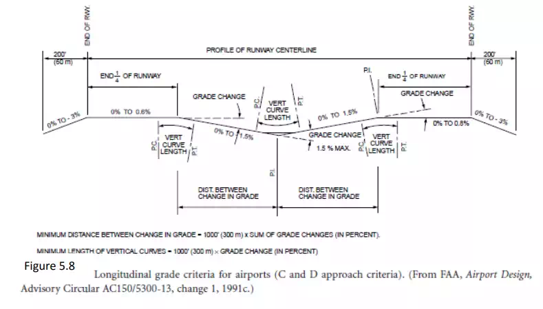
The desire at any airport site is to have the runways and taxiways as level as possible, allowing for drainage with the design of the transverse grade. In many locations the grading for a perfectly level site would be too expensive when most aircraft can easily accept 1% grade. Where longitudinal grades are used, parabolic vertical curves are used for geometric design, as shown in Fig. 5.8. The penalty for gradients is to reduce the effective runway length by 10 feet per foot of difference between maximum and minimum elevation of the runway [FAA, 1992]. and the lowest point along the runway of 70 feet, the effective runway length for MATOW calculations would be 9500 (10,200 – 70 ¥¥10) feet.
Line of Sight
The line-of-sight requirements also determine the acceptable profile of the runway. Any two points 5 feet above the runway centerline must be mutually visible for the entire runway or if on a parallel runway or taxiway for one half of the runway. Likewise, there needs to be a clear line of sight at the intersection of two runways, two taxiways, and taxiways that cross an active runway. Most line-of-sight requirements are within 800 to 1350 feet of the intersection, depending on the configuration.
Transverse Gradients
The transverse gradients are important to ensure adequate drainage from the runways and the taxiways. The plan view shown in Fig. 5.7 indicates the typical gradients that are included in runways and taxiways. The chief concern is drainage and the line of sight to adjacent runways or taxiways.

Drainage
Drainage on the airport surface is a prime requisite for operational safety and pavement durability. The drainage design is handled like most drainage for streets and highways. Avoidance of ponding and erosion of slopes that would weaken pavement foundations is critical for design. Because of the need for quick and total water removal over the vast, relatively flat airport surface, an integrated drainage system is a must. Runoff is removed from the airport by means of surface gradients, ditches, inlets, an underground system of pipes, and retention ponds. Because of their large contiguous area, aprons are critical and must have an adequate sewer system. Runoff water treatment is required when there are fuel spills or during the winter, when a deicing chemical is used.
Airport Lighting and Signing
Runway
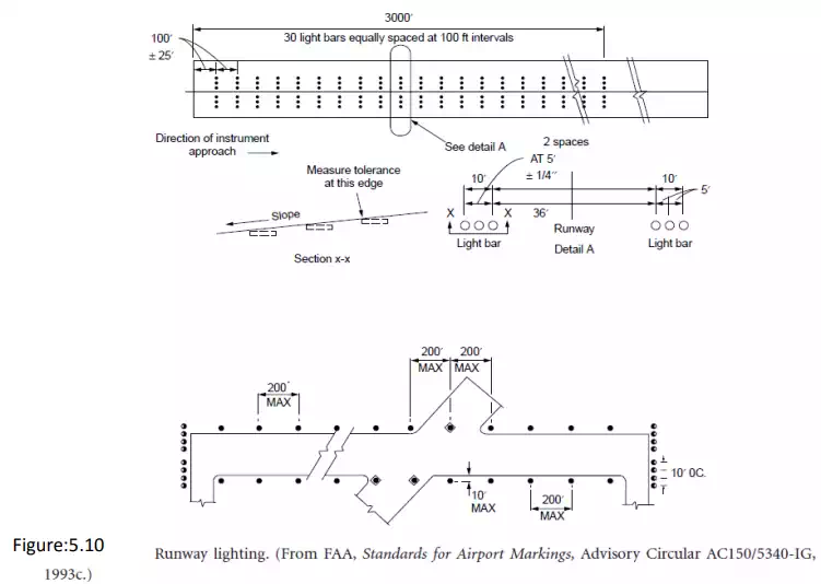
Lighting and signing of the runway shown in Fig. 5.10 provide the pilot visual cues to ensure alignment with the runway, lateral displacement, and distance along the runway. Runway edge lights standing no more than 30 inches and no more than 10 ft from the runway edge are 200 ft or less apart and are white, except for the last 2000 ft of runway, when they show yellow. Centerline lights are white and set 2 ft off the centerline of the runway, except for the last 3000 ft. In this area they are alternating red and white for 2000 ft, and they are red 1000 ft from the runway end. When aircraft are approaching the runway to land, the pilot determines the threshold because it is marked by a bar of green lights. However, those lights show red when aircraft approach the end of the runway from the other direction. As shown in Fig. 5.11 painted markings also indicate where the aircraft is relative to distance past the threshold. Exits, particularly high-speed exits, are clearly marked by signs placed at a distance of 1200 to 1500 ft before the exit