Runway Length
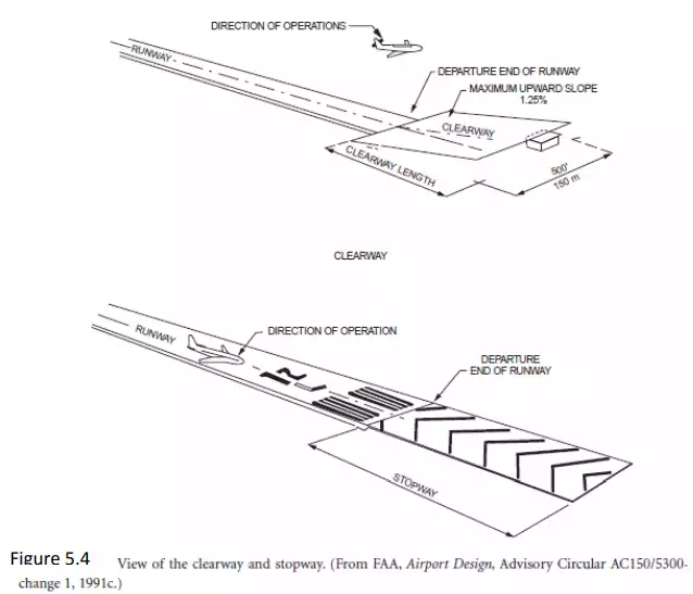
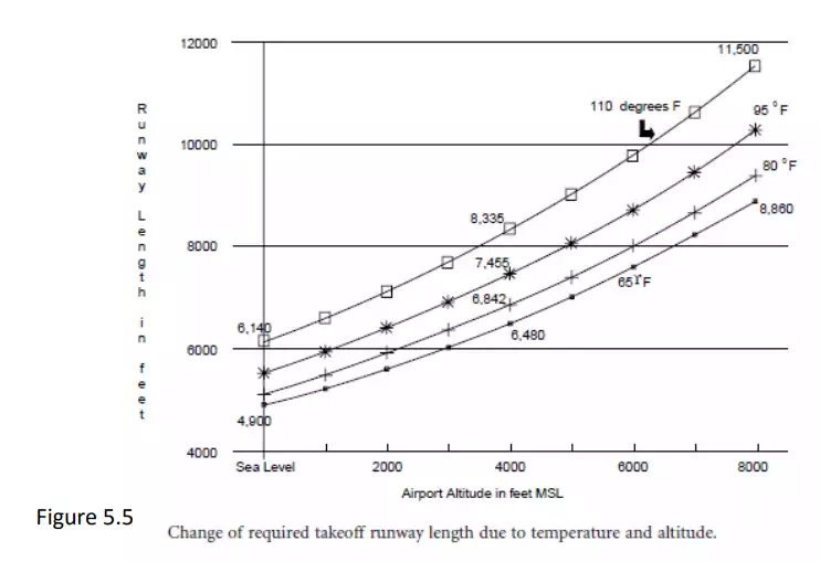
The length of the runway is determined by the aircraft, maximum takeoff weights, engine capabilities, landing and braking capabilities, flap settings, and required safety factors. For example, the runway length for landing must be capable of permitting safe braking if touchdown occurs one third the length of the runway past the threshold. The runway must also be long enough to meet the obstacle-free capability to permit each aircraft to take off with one engine out. The stopping zone must include ample stopping distance in case the pilot chooses to abort takeoff just before rotating to become airborne (called stopway). As discussed, the runway safety areas are a must for airport control. Figure 5.4 shows the stopway, to prevent accidents at the end of the runway, and the clearway, also called the runway protection zone. The altitude of the airport and the temperature also have a significant impact on the airport runway length, because lift capability is proportional to the air density, which diminishes as the altitude and temperature increase. Figure 5.5 illustrates how dramatic that change is for a Boeing 727-200 with a JT8D-15 engine, a takeoff weight of 150,000 pounds, and its wing flaps set at 20 degrees. The requirement for longer runways increases significantly as the altitude of the site above sea level increases. At an average temperature of 65 degrees Fahrenheit, the increase is from 4900 feet at sea level to 8660 feet at an altitude of 8000 feet, or about 370 feet of added runway for each 1000-foot increase in altitude.
Runway and Taxiway Width and Clearance Design Standards
The FAA has developed a set of standard dimensions that determine runway width, separations between runways and taxiways, safety areas around runways and taxiways, shoulder width (possible areas of lessthan- full-strength pavement), pads to deflect jet blast, object-free areas, and the like. These standards are a function of approach speed and aircraft size. Figure 5.6 presents the overall dimensions that are involved in parallel railways and taxiways. Figure 5.7 shows the plan view of major runway parabolic vertical curves are used for geometric design, as shown in Fig. 5.8.