Turn-and-Slip Indicator
The turn-and-slip indicator may also be referred to as the turnand-bank indicator, or needle-and-ball indicator. Regardless, it shows the correct execution of a turn while banking the aircraft and indicates movement about the vertical axis of the aircraft (yaw). Most turn-and-slip indicators are located below the airspeed indicator of the instrument panel basic T, just to the left of the direction indicator.
The turn-and-slip indicator is actually two separate devices built into the same instrument housing: a turn indicator pointer and slip indicator ball. The turn pointer is operated by a gyro that can be driven by a vacuum, air pressure, or by electricity. The ball is a completely independent device. It is a round agate, or steel ball, in a glass tube filled with dampening fluid. It moves in response to gravity and centrifugal force experienced in a turn.
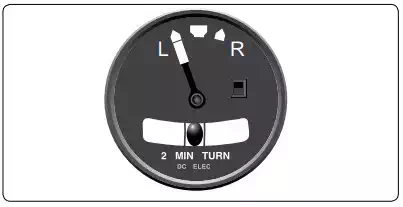
Turn indicators vary. They all indicate the rate at which the aircraft is turning. Three degrees of turn per second cause an aircraft to turn 360° in 2 minutes. This is considered a standard turn. This rate can be indicated with marks right and left of the pointer, which normally rests in the vertical position. Sometimes, no marks are present and the width of the pointer is used as the calibration device. In this case, one pointer width deflection from vertical is equal to the 3° per second standard 2-minute turn rate. Faster aircraft tend to turn more slowly and have graduations or labels that indicate 4-minute turns. In other words, a pointer’s width or alignment with a graduation mark on this instrument indicates that the aircraft is turning a 1-1 ⁄2° per second and completes a 360° turn in 4 minutes. It is customary to placard the instrument face with words indicating whether it is a 2-or 4-minute turn indicator.
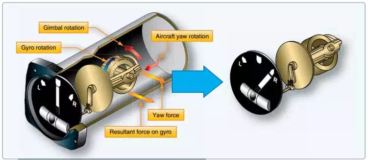
The turn pointer indicates the rate at which an aircraft is turning about its vertical axis. It does so by using the precession of a gyro to tilt a pointer. The gyro spins in a vertical plane aligned with the longitudinal axis of the aircraft. When the aircraft rotates about its vertical axis during a turn, the force experienced by the spinning gyro is exerted about the vertical axis. Due to precession, the reaction of the gyro rotor is 90° further around the gyro in the direction of spin. This means the reaction to the force around the vertical axis is movement around the longitudinal axis of the aircraft. This causes the top of the rotor to tilt to the left or right. The pointer is attached with linkage that makes the pointer deflect in the opposite direction, which matches the direction of turn. So, the aircraft’s turn around the vertical axis is indicated around the longitudinal axis on the gauge. This is intuitive to the pilot when regarding the instrument, since the pointer indicates in the same direction as the turn.
The slip indicator (ball) part of the instrument is an inclinometer. The ball responds only to gravity during coordinated straight-and-level flight. Thus, it rests in the lowest part of the curved glass between the reference wires. When a turn is initiated and the aircraft is banked, both gravity and the centrifugal force of the turn act upon the ball. If the turn is coordinated, the ball remains in place. Should a skidding turn exist, the centrifugal force exceeds the force of gravity on the ball and it moves in the direction of the outside of the turn. During a slipping turn, there is more bank than needed, and gravity is greater than the centrifugal force acting on the ball. The ball moves in the curved glass toward the inside of the turn.
As mentioned previously, often power for the turn-andslip indicator gyro is electrical if the attitude and direction indicators are vacuum powered. This allows limited operation off battery power should the vacuum system and the electric generator fail. The directional and attitude information from the turn-and-slip indicator, combined with information from the pitot static instruments, allow continued safe emergency operation of the aircraft.
Electrically powered turn-and-slip indicators are usually DC powered. Vacuum-powered turn-and-slip indicators are usually run on less vacuum (approximately 2 "Hg) than fully gimbaled attitude and direction indicators. Regardless, proper vacuum must be maintained for accurate turn rate information to be displayed.