Principles of Gyroscopic Instruments
Mechanical Gyros
Three of the most common flight instruments, the attitude indicator, heading indicator, and turn needle of the turn-andbank indicator, are controlled by gyroscopes. To understand how these instruments operate, knowledge of gyroscopic principles and instrument power systems is required. A mechanical gyroscope, or gyro, is comprised of a wheel or rotor with its mass concentrated around its perimeter. The rotor has bearings to enable it to spin at high speeds.
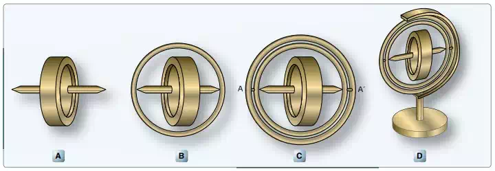
Different mounting configurations are available for the rotor and axle, which allow the rotor assembly to rotate about one or two axes perpendicular to its axis of spin. To suspend the rotor for rotation, the axle is first mounted in a supporting ring. . [Figure A]
Different mounting configurations are available for the rotor and axle, which allow the rotor assembly to rotate about one or two axes perpendicular to its axis of spin. To suspend the rotor for rotation, the axle is first mounted in a supporting ring. [Figure B]. If brackets are attached 90° around the supporting ring from where the spin axle attached, the supporting ring and rotor can both move freely 360°. When in this configuration, the gyro is said to be a captive gyro. It can rotate about only one axis that is perpendicular to the axis of spin. [Figure C].
The supporting ring can also be mounted inside an outer ring. The bearing points are the same as the bracket just described, 90° around the supporting ring from where the spin axle attached. Attachment of a bracket to this outer ring allows the rotor to rotate in two planes while spinning. Both of these are perpendicular to the spin axis of the rotor. The plane that the rotor spins in due to its rotation about its axle is not counted as a plane of rotation.
A gyroscope with this configuration, two rings plus the mounting bracket, is said to be a free gyro because it is free to rotate about two axes that are both perpendicular to the rotor’s spin axis. [Figure D] As a result, the supporting ring with spinning gyro mounted inside is free to turn 360° inside the outer ring.
Unless the rotor of a gyro is spinning, it has no unusual properties; it is simply a wheel universally mounted. When the rotor is rotated at a high speed, the gyro exhibits a couple of unique characteristics. The first is called gyroscopic rigidity, or rigidity in space. This means that the rotor of a free gyro always points in the same direction no matter which way the base of the gyro is positioned.
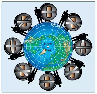
Once spinning, a free gyro rotor stays oriented in the same position in space despite the position or location of its base.
Gyroscopic rigidity depends upon several design factors:
1. Weight—for a given size, a heavy mass is more resistant to disturbing forces than a light mass.
2. Angular velocity—the higher the rotational speed, the greater the rigidity or resistance is to deflection.
3. Radius at which the weight is concentrated— maximum effect is obtained from a mass when its principal weight is concentrated near the rim, rotating at high speed.
4. Bearing friction—any friction applies a deflecting force to a gyro. Minimum bearing friction keeps deflecting forces at a minimum.
This characteristic of gyros to remain rigid in space is exploited in the attitude-indicating instruments and the directional indicators that use gyros. Precession is a second important characteristic of gyroscopes. By applying a force to the horizontal axis of the gyro, a unique phenomenon occurs. The applied force is resisted. Instead of responding to the force by moving about the horizontal axis, the gyro moves in response about its vertical axis. Stated another way, an applied force to the axis of the spinning gyro does not cause the axis to tilt. Rather, the gyro responds as though the force was applied 90° around in the direction of rotation of the gyro rotor. The gyro rotates rather than tilts. [Figure Below] This predictable controlled precession of a gyroscope is utilized in a turn and bank instrument.
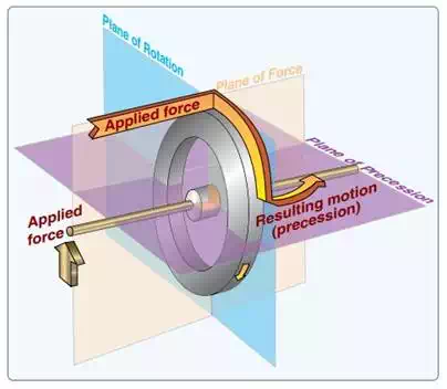
When a force is applied to a spinning gyroscope, it reacts as though the force came from 90° further around the rotor in the direction it is spinning. The plane of the applied force, the plane of the rotation, and the plane in which the gyro responds (known as the plane of precession), are all perpendicular to each other.