Twin-Engine Aircraft Vacuum System Operation
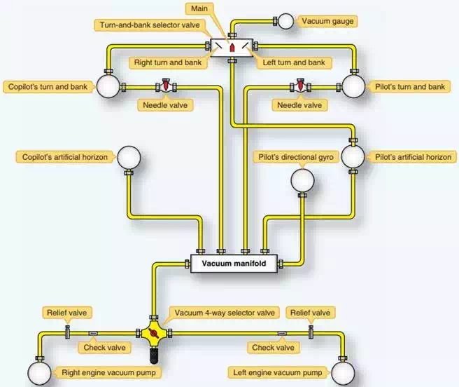
Twin-engine aircraft vacuum systems are more complicated. They contain an engine-driven vacuum pump on each engine. The associated lines and components for each pump are isolated from each other and act as two independent vacuum systems. The vacuum lines are routed from each vacuum pump through a vacuum relief valve and through a check valve to the vacuum four-way selector valve. The four-way valve permits either pump to supply a vacuum manifold. From the manifold, flexible hoses connect the vacuumoperated instruments into the system. To reduce the vacuum for the turn and bank indicators, needle valves are included in both lines to these units. Lines to the artificial horizons and the directional gyro receive full vacuum. From the instruments, lines are routed to the vacuum gauge through a turn and bank selector valve. This valve has three positions: main, left turn and bank (T&B), and right T&B. In the main position, the vacuum gauge indicates the vacuum in the lines of the artificial horizons and directional gyro. In the other positions, the lower value of vacuum for the turn and bank indicators can be read.
A schematic of this twin-engine aircraft vacuum system is shown in Figure below. Note the following components: two engine-driven pumps, two vacuum relief valves, two flapper type check valves, a vacuum manifold, a vacuum restrictor for each turn and bank indicator, an engine four-way selector valve, one vacuum gauge, and a turn-and-bank selector valve. Not shown are system and individual instrument filters. A drain line may also be installed at the low point in the system.