Typical Pump-Driven System
The following components are found in a typical vacuum system for gyroscopic power supply. A brief description is given of each. Refer to the figures for detailed illustrations. Air-oil separator—oil and air in the vacuum pump are exhausted through the separator, which separates the oil from the air; the air is vented overboard and the oil is returned to the engine sump. This component is not present when a dry-type vacuum pump is used. The self-lubricating nature of the pump vanes requires no oil.
Vacuum regulator or suction relief valve—since the system capacity is more than is needed for operation of the instruments, the adjustable vacuum regulator is set for the vacuum desired for the instruments. Excess suction in the instrument lines is reduced when the spring-loaded valve opens to atmospheric pressure.
A vacuum regulator, also known as a suction relief valve, includes a foam filter. To relieve vacuum, outside air of a higher pressure must be drawn into the system. This air must be clean to prevent damage to the pump
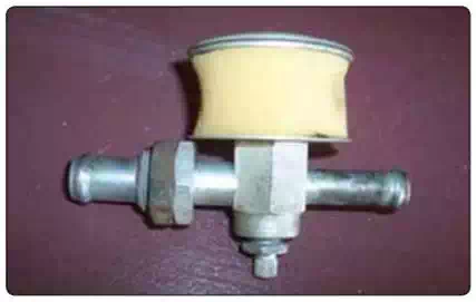
Gate check valve—prevents possible damage to the instruments by engine backfire that would reverse the flow of air and oil from the pump.
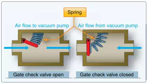
Gate check valve used to prevent vacuum system damage from engine backfire.
Selector valve—In twin-engine aircraft having vacuum pumps driven by both engines, the alternate pump can be selected to provide vacuum in the event of either engine or pump failure, with a check valve incorporated to seal off the failed pump.
Restrictor valve—Since the turn needle of the turn and bank indicator operates on less vacuum than that required by the other instruments, the vacuum in the main line must be reduced for use by this instrument. An in-line restrictor valve performs this function. This valve is either a needle valve or a spring-loaded regulating valve that maintains a constant, reduced vacuum for the turn-and-bank indicator.
Air filter—A master air filter screens foreign matter from the air flowing through all the gyro instruments. It is an extremely import filter requiring regular maintenance. Clogging of the master filter reduces airflow and causes a lower reading on the suction gauge. Each instrument is also provided with individual filters. In systems with no master filter that rely only upon individual filters, clogging of a filter does not necessarily show on the suction gauge.
Suction gauge—a pressure gauge which indicates the difference between the pressure inside the system and atmospheric or cockpit pressure. It is usually calibrated in inches of mercury. The desired vacuum and the minimum and maximum limits vary with gyro system design. If the desired vacuum for the attitude and heading indicators is 5 inches and the minimum is 4.6 inches, a reading below the latter value indicates that the airflow is not spinning the gyros fast enough for reliable operation. In many aircraft, the system provides a suction gauge selector valve permitting the pilot to check the vacuum at several points in the system.
Suction/vacuum pressures discussed in conjunction with the operation of vacuum systems are actually negative pressures, indicated as inches of mercury below that of atmospheric pressure. The minus sign is usually not presented, as the importance is placed on the magnitude of the vacuum developed. In relation to an absolute vacuum (0 psi or 0 "Hg), instrument vacuum systems have positive pressure.
Figure below shows a typical engine-driven pump vacuum system containing the above components. A pump capacity of approximately 10"Hg at engine speeds above 1,000 rpm is normal. Pump capacity and pump size vary in different aircraft, depending on the number of gyros to be operated.
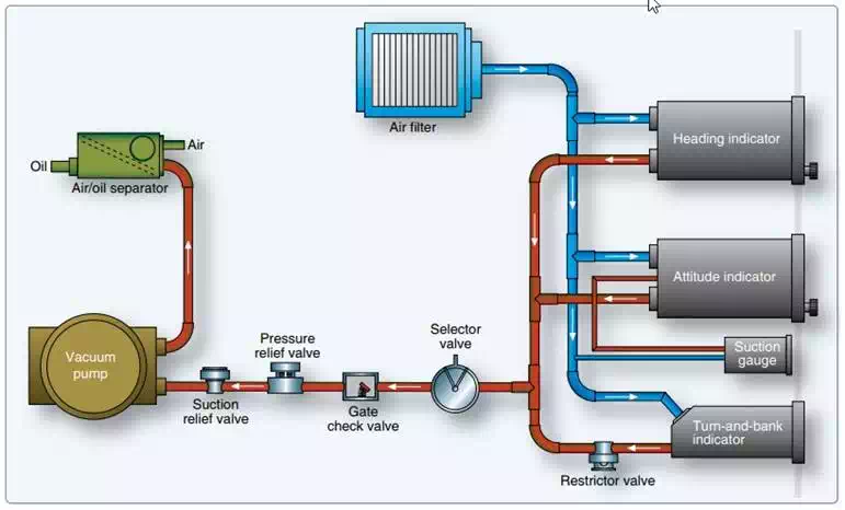
A typical pump-driven vacuum system for powering gyroscopic instruments.