Turbine Gas Temperature Indicating Systems
EGT is a critical variable of turbine engine operation. The EGT indicating system provides a visual temperature indication in the cockpit of the turbine exhaust gases as they leave the turbine unit. In certain turbine engines, the temperature of the exhaust gases is measured at the entrance to the turbine unit. This is referred to as a turbine inlet temperature (TIT) indicating system.
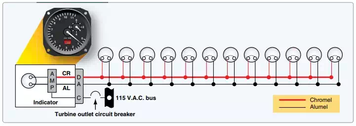
Several thermocouples are used to measure EGT or TIT. They are spaced at intervals around the perimeter of the engine turbine casing or exhaust duct. The tiny thermocouple voltages are typically amplified and used to energize a servomotor that drives the indicator pointer. Gearing a digital drum indication off of the pointer motion is common. [Figure below] The EGT indicator shown is a hermetically sealed unit. The instrument’s scale ranges from 0 °C to 1,200 °C, with a vernier dial in the upper right-hand corner and a power off warning flag located in the lower portion of the dial.
A TIT indicating system provides a visual indication at the instrument panel of the temperature of gases entering the turbine. Numerous thermocouples can be used with the average voltage representing the TIT. Dual thermocouples exist containing two electrically independent junctions within a single probe. One set of these thermocouples is paralleled to transmit signals to the cockpit indicator. The other set of parallel thermocouples provides temperature signals to engine monitoring and control systems. Each circuit is electrically independent, providing dual system reliability.
A schematic for the turbine inlet temperature system for one engine of a four-engine turbine aircraft is shown in Figure Below. Circuits for the other three engines are identical to this system. The indicator contains a bridge circuit, a chopper circuit, a two-phase motor to drive the pointer, and a feedback potentiometer. Also included are a voltage reference circuit, an amplifier, a power-off flag, a power supply, and an over temperature warning light. Output of the amplifier energizes the variable field of the two-phase motor that positions the indicator main pointer and a digital indicator. The motor also drives the feedback potentiometer to provide a humming signal to stop the drive motor when the correct pointer position, relative to the temperature signal, has been reached. The voltage reference circuit provides a closely regulated reference voltage in the bridge circuit to preclude error from input voltage variation to the indicator power supply.
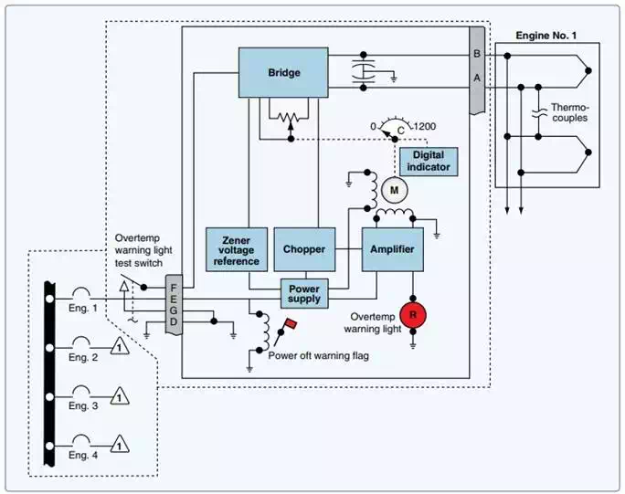
A typical analog turbine inlet temperature indicating system.
The overtemperature warning light in the indicator illuminates when the TIT reaches a predetermined limit. An external test switch is usually installed so that over temperature warning lights for all the engines can be tested at the same time. When the test switch is operated, an overtemperature signal is simulated in each indicator temperature control bridge circuit.
Digital cockpit instrumentation systems need not employ resistance-type indicators and adjusted servo-driven thermocouple gauges to provide the pilot with temperature information. Sensor resistance and voltage values are input to the appropriate computer, where they are adjusted, processed, monitored, and output for display on cockpit display panels. They are also sent for use by other computers requiring temperature information for the control and monitoring of various integrated systems.