Thermocouple Temperature Indicators
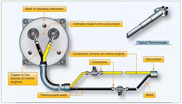
A thermocouple is a circuit or connection of two unlike metals. The metals are touching at two separate junctions. If one of the junctions is heated to a higher temperature than the other, an electromotive force is produced in the circuit. This voltage is directly proportional to the temperature. So, by measuring the amount of electromotive force, temperature can be determined. A voltmeter is placed across the colder of the two junctions of the thermocouple. It is calibrated in degrees Fahrenheit or Celsius, as needed. The hotter the hightemperature junction (hot junction) becomes, the greater the electromotive force produced, and the higher the temperature indication on the meter.
Thermocouples combine two unlike metals that cause current flow when heated.
Thermocouples are used to measure high temperatures. Two common applications are the measurement of cylinder head temperature (CHT) in reciprocating engines and exhaust gas temperature (EGT) in turbine engines. Thermocouple leads are made from a variety of metals, depending on the maximum temperature to which they are exposed. Iron and constantan, or copper and constantan, are common for CHT measurement. Chromel and alumel are used for turbine EGT thermocouples.
The amount of voltage produced by the dissimilar metals when heated is measured in millivolts. Therefore, thermocouple leads are designed to provide a specific amount of resistance in the thermocouple circuit (usually very little). Their material, length, or cross-sectional size cannot be altered without compensation for the change in total resistance that would result. Each lead that makes a connection back to the voltmeter must be made of the same metal as the part of the thermocouple to which it is connected. For example, a copper wire is connected to the copper portion of the hot junction and a constantan wire is connected to the constantan part.
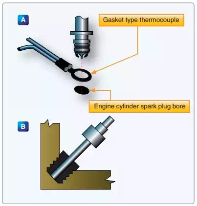
The hot junction of a thermocouple varies in shape depending on its application. Two common types are the gasket and the bayonet. In the gasket type, two rings of the dissimilar metals are pressed together to form a gasket that can be installed under a spark plug or cylinder hold down nut. In the bayonet type, the metals come together inside a perforated protective sheath. Bayonet thermocouples fit into a hole or well in a cylinder head. On turbine engines, they are found mounted on the turbine inlet or outlet case and extend through the case into the gas stream. Note that for CHT indication, the cylinder chosen for the thermocouple installation is the one that runs the hottest under most operating conditions. The location of this cylinder varies with different engines.
The cold junction of the thermocouple circuit is inside the instrument case. Since the electromotive force set up in the circuit varies with the difference in temperature between the hot and cold junctions, it is necessary to compensate the indicator mechanism for changes in cockpit temperature which affect the cold junction. This is accomplished by using a bimetallic spring connected to the indicator mechanism. This actually works the same as the bimetallic thermometer described previously. When the leads are disconnected from the indicator, the temperature of the cockpit area around the instrument panel can be read on the indicator dial. [Figure below] Numeric LED indictors for CHT are also common in modern aircraft.
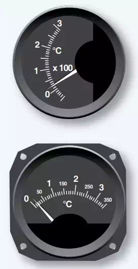
Typical thermocouple temperature indicators