Pressure Measuring Instruments
A number of instruments inform the pilot of the aircraft’s condition and flight situations through the measurement of pressure. Pressure-sensing instruments can be found in the flight group and the engine group. They can be either direct reading or remote sensing. These are some of the most critical instruments on the aircraft and must accurately inform the pilot to maintain safe operations. Pressure measurement involves some sort of mechanism that can sense changes in pressure. A technique for calibration and displaying the information is then added to inform the pilot. The type of pressure needed to be measured often makes one sensing mechanism more suited for use in a particular instance. The three fundamental pressure-sensing mechanisms used in aircraft instrument systems are the Bourdon tube, the diaphragm or bellows, and the solid-state sensing device.
A Bourdon tube is illustrated in Figure. The open end of this coiled tube is fixed in place and the other end is sealed and free to move. When a fluid that needs to be measured is directed into the open end of the tube, the unfixed portion of the coiled tube tends to straighten out. The higher the pressure of the fluid, the more the tube straightens. When the pressure is reduced, the tube recoils. A pointer is attached to this moving end of the tube, usually through a linkage of small shafts and gears. By calibrating this motion of the straightening tube, a face or dial of the instrument can be created. Thus, by observing the pointer movement along the scale of the instrument face positioned behind it, pressure increases and decreases are communicated to the pilot.
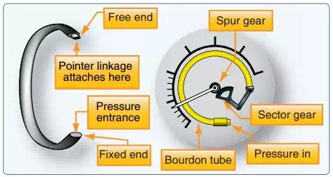
The Bourdon tube is one of the basic mechanisms for sensing pressure.
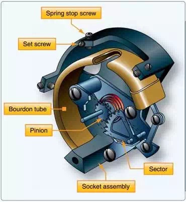
The Bourdon tube is the internal mechanism for many pressure gauges used on aircraft. When high pressures need to be measured, the tube is designed to be stiff. Gauges used to indicate lower pressures use a more flexible tube that uncoils and coils more readily. Most Bourdon tubes are made from brass, bronze, or copper. Alloys of these metals can be made to coil and uncoil the tube consistently numerous times.
Bourdon tube gauges are simple and reliable. Some of the instruments that use a Bourdon tube mechanism include the engine oil pressure gauge, hydraulic pressure gauge, oxygen tank pressure gauge, and deice boot pressure gauge. Since the pressure of the vapor produced by a heated liquid or gas increases as temperature increases, Bourdon tube mechanisms can also be used to measure temperature. This is done by calibrating the pointer connecting linkage and relabeling the face of the gauge with a temperature scale. Oil temperature gauges often employ Bourdon tube mechanisms.
The Bourdon tube mechanism can be used to measure pressure or temperature by recalibrating the pointer’s connecting linkage and scaling instrument face to read in degrees Celsius or Fahrenheit.
Since the sensing and display of pressure or temperature information using a Bourdon tube mechanism usually occurs in a single instrument housing, they are most often direct reading gauges. But the Bourdon tube sensing device can also be used remotely. Regardless, it is necessary to direct the fluid to be measured into the Bourdon tube. For example, a common direct-reading gauge measuring engine oil pressure and indicating it to the pilot in the cockpit is mounted in the instrument panel. A small length of tubing connects a pressurized oil port on the engine, runs though the firewall, and into the back of the gauge. This setup is especially functional on light, single-engine aircraft in which the engine is mounted just forward of the instrument panel in the forward end of the fuselage. However, a remote sensing unit can be more practical on twin-engine aircraft where the engines are a long distance from the cockpit pressure display. Here, the Bourdon tube’s motion is converted to an electrical signal and carried to the cockpit display via a wire. This is lighter and more efficient, eliminating the possibility of leaking fluids into the passenger compartment of the aircraft.
The diaphragm and bellows are two other basic sensing mechanisms employed in aircraft instruments for pressure measurement. The diaphragm is a hollow, thin-walled metal disk, usually corrugated. When pressure is introduced through an opening on one side of the disk, the entire disk expands. By placing linkage in contact against the other side of the disk, the movement of the pressurized diaphragm can be transferred to a pointer that registers the movement against the scale on the instrument face.
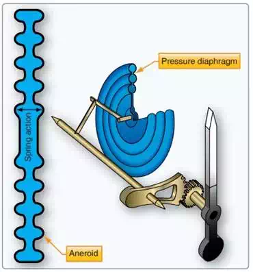
A diaphragm used for measuring pressure. An evacuated sealed diaphragm is called an aneroid.
Diaphragms can also be sealed. The diaphragm can be evacuated before sealing, retaining absolutely nothing inside. When this is done, the diaphragm is called an aneroid. Aneroids are used in many flight instruments. A diaphragm can also be filled with a gas to standard atmospheric pressure and then sealed. Each of these diaphragms has their uses, which are described in the next section. The common factor in all is that the expansion and contraction of the side wall of the diaphragm is the movement that correlates to increasing and decreasing pressure.
When a number of diaphragm chambers are connected together, the device is called a bellows. This accordionlike assembly of diaphragms can be very useful when measuring the difference in pressure between two gases, called differential pressure. Just as with a single diaphragm, it is the movement of the side walls of the bellows assembly that correlates with changes in pressure and to which a pointer linkage and gearing is attached to inform the pilot.
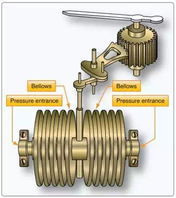
A bellows unit in a differential pressure gauge compares two different pressure values. End movement of the bellows away from the side with the highest pressure input occurs when the pressures in the bellows are not equal. The indicator linkage is calibrated to display the difference.
Diaphragms, aneroids, and bellows pressure sensing devices are often located inside the single instrument housing that contains the pointer and instrument dial read by the pilot on the instrument panel. Thus, many instruments that make use of these sensitive and reliable mechanisms are direct reading gauges. But, many remote sensing instrument systems also make use of the diaphragm and bellows. In this case, the sensing device containing the pressure sensitive diaphragm or bellows is located remotely on the engine or airframe. It is part of a transducer that converts the pressure into an electrical signal. The transducer, or transmitter, sends the signal to the gauge in the cockpit, or to a computer, for processing and subsequent display of the sensed condition. Examples of instruments that use a diaphragm or bellows in a direct reading or remote sensing gauge are the altimeter, vertical speed indicator, cabin differential pressure gauge (in pressurized aircraft), and manifold pressure gauge.
Solid-state microtechnology pressure sensors are used in modern aircraft to determine the critical pressures needed for safe operation. Many of these have digital output ready for processing by electronic flight instrument computers and other onboard computers. Some sensors send microelectric signals that are converted to digital format for use by computers. As with the analog sensors described above, the key to the function of solid-state sensors is their consistent property changes as pressure changes.
The solid-state sensors used in most aviation applications exhibit varying electrical output or resistance changes when pressure changes occur. Crystalline piezoelectric, piezoresistor, and semiconductor chip sensors are most common. In the typical sensor, tiny wires are embedded in the crystal or pressure-sensitive semiconductor chip. When pressure deflects the crystal(s), a small amount of electricity is created or, in the case of a semiconductor chip and some crystals, the resistance changes. Since the current and resistance changes vary directly with the amount of deflection, outputs can be calibrated and used to display pressure values.
Nearly all of the pressure information needed for engine, airframe, and flight instruments can be captured and/or calculated through the use of solid-state pressure sensors in combination with temperature sensors. But continued use of aneroid devices for comparisons involving absolute pressure is notable. Solid-state pressure-sensing systems are remote sensing systems. The sensors are mounted on the aircraft at convenient and effective locations.