Electrical Temperature Measuring Indication
The use of electricity in measuring temperature is very common in aviation. The following measuring and indication systems can be found on many types of aircraft. Certain temperature ranges are more suitably measured by one or another type of system.
Electrical Resistance Thermometer
The principle parts of the electrical resistance thermometer are the indicating instrument, the temperature-sensitive element (or bulb), and the connecting wires and plug connectors. Electrical resistance thermometers are used widely in many types of aircraft to measure carburetor air, oil, free air temperatures, and more. They are used to measure low and medium temperatures in the –70 °C to 150 °C range.

A bimetallic outside air temperature gauge and its installation on a light aircraft.
For most metals, electrical resistance changes as the temperature of the metal changes. This is the principle upon which a resistance thermometer operates. Typically, the electrical resistance of a metal increases as the temperature rises. Various alloys have a high temperature-resistance coefficient, meaning their resistance varies significantly with temperature. This can make them suitable for use in temperature sensing devices. The metal resistor is subjected to the fluid or area in which temperature needs to be measured. It is connected by wires to a resistance measuring device inside the cockpit indicator. The instrument dial is calibrated in degrees Fahrenheit or Celsius as desired rather than in ohms. As the temperature to be measured changes, the resistance of the metal changes and the resistance measuring indicator shows to what extent.
A typical electrical resistance thermometer looks like any other temperature gauge. Indicators are available in dual form for use in multiengine aircraft. Most indicators are self-compensating for changes in cockpit temperature. The heat-sensitive resistor is manufactured so that it has a definite resistance for each temperature value within its working range. The temperature-sensitive resistor element is a length or winding made of a nickel/manganese wire or other suitable alloy in an insulating material. The resistor is protected by a closed-end metal tube attached to a threaded plug with a hexagonal head. [See Figure below] The two ends of the winding are brazed, or welded, to an electrical receptacle designed to receive the prongs of the connector plug.
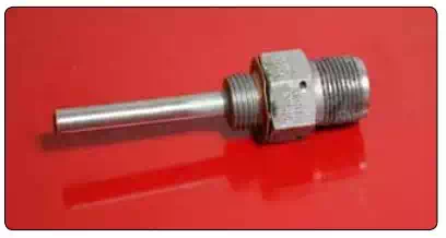
An electric resistance thermometer sensing bulb.
The indicator contains a resistance-measuring instrument. Sometimes it uses a modified form of the Wheatstonebridge circuit. The Wheatstone-bridge meter operates on the principle of balancing one unknown resistor against other known resistances. A simplified form of a Wheatstonebridge circuit is shown in Figure 10-69. Three equal values of resistance [Figure A, B, and C] are connected into a diamond shaped bridge circuit. A resistor with an unknown value [Figure D] is also part of the circuit. The unknown resistance represents the resistance of the temperature bulb of the electrical resistance thermometer system. A galvanometer is attached across the circuit at points X and Y.
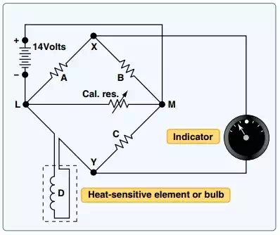
The internal structure of an electric resistance thermometer indicator features a bridge circuit, galvanometer, and variable resistor, which is outside the indicator in the form of the temperature sensor.
When the temperature causes the resistance of the bulb to equal that of the other resistances, no potential difference exists between points X and Y in the circuit. Therefore, no current flows in the galvanometer leg of the circuit. If the temperature of the bulb changes, its resistance also changes, and the bridge becomes unbalanced, causing current to flow through the galvanometer in one direction or the other. The galvanometer pointer is actually the temperature gauge pointer. As it moves against the dial face calibrated in degrees, it indicates temperature. Many indicators are provided with a zero adjustment screw on the face of the instrument. This adjusts the zeroing spring tension of the pointer when the bridge is at the balance point (the position at which the bridge circuit is balanced and no current flows through the meter).