Stall Warning and Angle of Attack (AOA) Indicators
An aircraft’s angle of attack (AOA) is the angle formed between the wing cord centerline and the relative wind. At a certain angle, airflow over the wing surfaces is insufficient to create enough lift to keep the aircraft flying, and a stall occurs. An instrument that monitors the AOA allows the pilot to avoid such a condition.
The simplest form of AOA indicator is a stall warning device that does not have a gauge located in the cockpit. It uses an aural tone to warn of an impending stall due to an increase in AOA. This is done by placing a reed in a cavity just aft of the leading edge of the wing. The cavity has an open passage to a precise point on the leading edge.
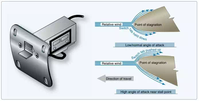
In flight, air flows over and under a wing. The point on the wing leading edge where the oncoming air diverges is known as the point of stagnation. As the AOA of the wing increases, the point of stagnation moves down below the open passage that leads inside the wing to the reed. Air flowing over the curved leading edge speeds up and causes a low pressure. This causes air to be sucked out of the inside of the wing through the passage. The reed vibrates as the air rushes by making a sound audible in the cockpit.
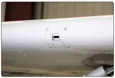
A reed-type stall warning device is located behind this opening in the leading edge of the wing. When the angle of attack increases to near the point of a stall, low-pressure air flowing over the opening causes a suction, which audibly vibrates the reed.
Another common device makes use of an audible tone as the AOA increases to near the point where the aircraft will stall. This stall warning device includes an electric switch that opens and closes a circuit to a warning horn audible in the cockpit. It may also be wired into a warning light circuit.
The switch is located near the point of stagnation on the wing leading edge. A small lightly sprung tab activates the switch. At normal AOA, the tab is held down by air that diverges at the point of stagnation and flows under the wing. This holds the switch open so the horn does not sound nor the warning light illuminate. As the AOA increases, the point of stagnation moves down. The divergent air that flows up and over the wing now pushes the tab upward to close the switch and complete the circuit to the horn or light.
A popular stall warning switch located in the wing leading edge.
A true AOA indicating system detects the local AOA of the aircraft and displays the information on a cockpit indicator. It also may be designed to furnish reference information to other systems on high-performance aircraft. The sensing mechanism and transmitter are usually located on the forward side of the fuselage. It typically contains a heating element to ensure ice-free operation. Signals are sent from the sensor to the cockpit or computer(s) as required. An AOA indicator may be calibrated in actual angle degrees, arbitrary units, percentage of lift used, symbols, or even fast/ slow.
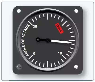
Angle of attack indicator.
There are two main types of AOA sensors in common use. Both detect the angular difference between the relative wind and the fuselage, which is used as a reference plane. One uses a vane, known as an alpha vane, externally mounted to the outside of the fuselage. It is free to rotate in the wind. As the AOA changes, air flowing over the vane changes its angle. The other uses two slots in a probe that extends out of the side of the fuselage into the airflow. The slots lead to different sides of movable paddles in a chamber of the unit just inside the fuselage skin. As the AOA varies, the air pressure ported by each of the slots changes and the paddles rotate to neutralize the pressures. The shaft upon which the paddles rotate connects to a potentiometer wiper contact that is part of the unit. The same is true of the shaft of the alpha vane. The changing resistance of the potentiometer is used in a balanced bridge circuit to signal a motor in the indicator to move the pointer proportional to the AOA.
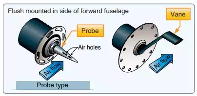
A slotted AOA probe and an alpha vane.
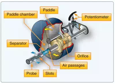
The internal structure of a slotted probe airstream direction detector.
Modern aircraft AOA sensor units send output signals to the ADC. There, the AOA data is used to create an AOA indication, usually on the primary flight display. AOA information can also be integrated with flap and slat position information to better determine the point of stall. Additionally, AOA sensors of the type described are subject to position error since airflow around the alpha vane and slotted probe changes somewhat with airspeed and aircraft attitude. The errors are small, but can be corrected in the ADC.
To incorporate a warning of an impending stall, many AOA systems signal a stick shaker motor that literally shakes the control column to warn the pilot as the aircraft approaches a stall condition. Electrical switches are actuated in the AOA indicator at various preset AOA to activate the motor that drives an unbalanced weighted ring, causing the column to shake. Some systems include a stick pusher actuator that pushes the control yoke forward, lowering the nose of the aircraft when the critical AOA is approached. Regardless of the many existing variations for warning of an impending stall, the AOA system triggers all stall warnings in high performance aircraft.