Electric Tachometers
It is not practical to use a mechanical linkage between the engine and the rpm indicator on aircraft with engines not mounted in the fuselage just forward of the instrument panel. Greater accuracy with lower maintenance is achieved through the use of electric tachometers. A wide variety of electric tachometer systems can be employed, so manufacturer’s instructions should be consulted for details of each specific tachometer system.
A popular electric tachometer system makes use of a small AC generator mounted to a reciprocating engine’s gear case or the accessory drive section of a turbine engine. As the engine turns, so does the generator. The frequency output of the generator is directly proportional to the speed of the engine. It is connected via wires to a synchronous motor in the indicator that mirrors this output. A drag cup, or drag disk link, is used to drive the indicator as in a mechanical tachometer.
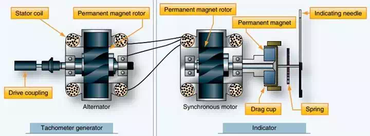
An electric tachometer system with synchronous motors and a drag cup indicator.
Two different types of generator units, distinguished by their type of mounting system, are shown in Figure below.
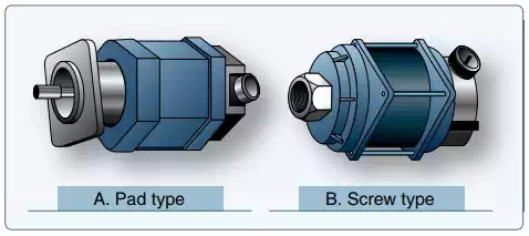
Different types of tach generators.
The dual tachometer consists of two tachometer indicator units housed in a single case. The indicator pointers show simultaneously, on one or two scales, the rpm of two engines. A dual tachometer on a helicopter often shows the rpm of the engine and the rpm of the main rotor. A comparison of the voltages produced by the two tach generators of this type of helicopter indicator gives information concerning clutch slippage. A third indication showing this slippage is sometimes included in the helicopter tachometer.

A helicopter tachometer with engine rpm, rotor rpm, and slippage indications.
Some turbine engines use tachometer probes for rpm indication, rather than a tach generator system. They provide a great advantage in that there are no moving parts. They are sealed units that are mounted on a flange and protrude into the compressor section of the engine. A magnetic field is set up inside the probe that extends through pole pieces and out the end of the probe. A rotating gear wheel, which moves at the same speed as the engine compressor shaft, alters the magnetic field flux density as it moves past the pole pieces at close proximity. This generates voltage signals in coils inside the probe. The amplitude of the EMF signals vary directly with the speed of the engine.
The tachometer probe’s output signals need to be processed in a remotely located module. They must also be amplified to drive a servo motor type indicator in the cockpit. They may also be used as input for an automatic power control system or a flight data acquisition system.
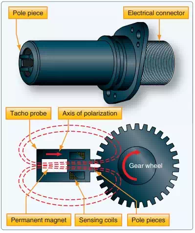
A tacho probe has no moving parts. The rate of magnetic flux field density change is directly related to engine speed.