Mechanical Tachometers
Mechanical tachometer indicating systems are found on small, single-engine light aircraft in which a short distance exists between the engine and the instrument panel. They consist of an indicator connected to the engine by a flexible drive shaft. The drive shaft is geared into the engine so that when the engine turns, so does the shaft. The indicator contains a flyweight assembly coupled to a gear mechanism that drives a pointer. As the drive shaft rotates, centrifugal force acts on the flyweights and moves them to an angular position. This angular position varies with the rpm of the engine. The amount of movement of the flyweights is transmitted through the gear mechanism to the pointer. The pointer rotates to indicate this movement on the tachometer indicator, which is directly related to the rpm of the engine.
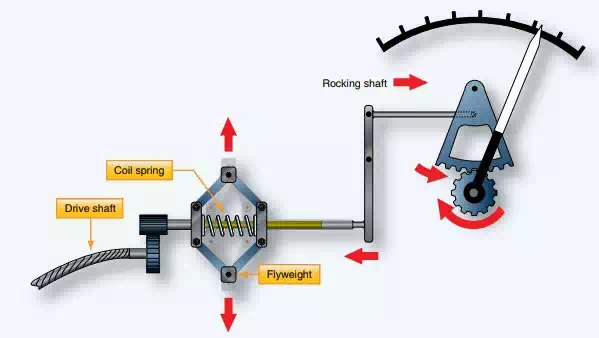
The simplified mechanism of a flyweight type mechanical tachometer.
A more common variation of this type of mechanical tachometer uses a magnetic drag cup to move the pointer in the indicator. As the drive shaft turns, it rotates a permanent magnet in a close-tolerance aluminum cup. A shaft attached to the indicating point is attached to the exterior center of the cup. As the magnet is rotated by the engine flex drive cable, its magnetic field cuts through the conductor surrounding it, creating eddy currents in the aluminum cup. This current flow creates its own magnetic field, which interacts with the rotating magnet’s flux field. The result is that the cup tends to rotate, and with it, the indicating pointer. A calibrated restraining spring limits the cup’s rotation to the arc of motion of the pointer across the scale on the instrument face.
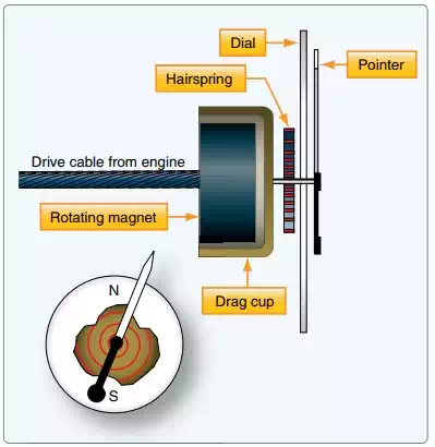
A simplified magnetic drag cup tachometer indicating device.