DC Selsyn Systems
On aircraft with direct current (DC) electrical systems, the DC selsyn system is widely used. As mentioned, the selsyn system consists of a transmitter, an indicator, and connecting wires. The transmitter consists of a circular resistance winding and a rotatable contact arm. The rotatable contact arm turns on a shaft in the center of the resistance winding. The two ends of the arm are brushes and always touch the winding on opposite sides.
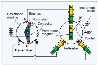
A schematic of a DC selsyn synchro remote indicating system.
On position indicating systems, the shaft to which the contact arm is fastened protrudes through the end of transmitter housing and is attached to the unit whose position is to be transmitted (e.g., flaps, landing gear). The transmitter is often connected to the moving unit through a mechanical linkage. As the unit moves, it causes the transmitter shaft to turn. The arm is turned so that voltage is applied through the brushes to any two points around the circumference of the resistance winding. The rotor shaft of DC selsyn systems, measuring other kinds of data, operates the same way, but may not protrude outside of the housing. The sensing device, which imparts rotary motion to the shaft, could be located inside the transmitter housing.
Referring to Figure above, note that the resistance winding of the transmitter is tapped off in three fixed places, usually 120° apart. These taps distribute current through the toroidial windings of the indicator motor. When current flows through these windings, a magnetic field is created. Like all magnetic fields, a definite north and south direction to the field exists. As the transmitter rotor shaft is turned, the voltage-supplying contact arm moves. Because it contacts the transmitter resistance winding in different positions, the resistance between the supply arm and the various tapoffs changes. This causes the voltage flowing through the tapoffs to change as the resistance of sections of the winding become longer or shorter. The result is that varied current is sent via the tapoffs to the three windings in the indicator motor.
The resultant magnetic field created by current flowing through the indicator coils changes as each receives varied current from the tapoffs. The direction of the magnetic field also changes. Thus, the direction of the magnetic field across the indicating element corresponds in position to the moving arm in the transmitter. A permanent magnet is attached to the centered rotor shaft in the indicator, as is the indicator pointer. The magnet aligns itself with the direction of the magnetic field and the pointer does as well. Whenever the magnetic field changes direction, the permanent magnet and pointer realign with the new position of the field. Thus, the position of the aircraft device is indicated.
Landing gear contain mechanical devices that lock the gear up, called an up-lock, or down, called a down-lock. When the DC selsyn system is used to indicate the position of the landing gear, the indicator can also show that the up-lock or down-lock is engaged. This is done by again varying the current flowing through the indicator’s coils. Switches located on the actual locking devices close when the locks engage. Current from the selsyn system described above flows through the switch and a small additional circuit. The circuit adds an additional resistor to one of the transmitter winding sections created by the rotor arm and a tapoff. This changes the total resistance of that section. The result is a change in the current flowing through one of the indicator’s motor coils. This, in turn, changes the magnetic field around that coil. Therefore, the combined magnetic field created by all three motor coils is also affected, causing a shift in the direction of the indicator’s magnetic field. The permanent magnet and pointer align with the new direction and shift to the locked position on the indicator dial. Figure below shows a simplified diagram of a lock switch in a three-wire selsyn system and an indicator dial.
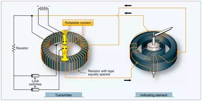
A lock switch circuit can be added to the basic DC selsyn synchro system when used to indicate landing gear position and up- and down-locked conditions on the same indicator.