Airspeed Indicators
The airspeed indicator is another primary flight instrument that is also a differential pressure gauge. Ram air pressure from the aircraft’s pitot tube is directed into a diaphragm in an analog airspeed instrument case. Static air pressure from the aircraft static vent(s) is directed into the case surrounding the diaphragm. As the speed of the aircraft varies, the ram air pressure varies, expanding or contracting the diaphragm. Linkage attached to the diaphragm causes a pointer to move over the instrument face, which is calibrated in knots or miles per hour (mph).
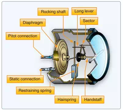
An airspeed indicator is a differential pressure gauge that compares ram air pressure with static pressure.
The relationship between the ram air pressure and static air pressure produces the indication known as indicated airspeed. As with the altimeter, there are other factors that must be considered in measuring airspeed throughout all phases of flight. These can cause inaccurate readings or indications that are not useful to the pilot in a particular situation. In analog airspeed indicators, the factors are often compensated for with ingenious mechanisms inside the case and on the instrument dial face. Digital flight instruments can have calculations performed in the ADC so the desired accurate indication is displayed.
While the relationship between ram air pressure and static air pressure is the basis for most airspeed indications, it can be more accurate. Calibrated airspeed takes into account errors due to position error of the pitot static pickups. It also corrects for the nonlinear nature of the pitot static pressure differential when it is displayed on a linear scale. Analog airspeed indicators come with a correction chart that allows cross-referencing of indicated airspeed to calibrated airspeed for various flight conditions. These differences are typically very small and often are ignored. Digital instruments have these corrections performed in the ADC.
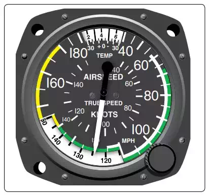
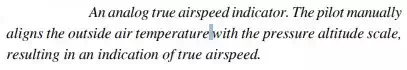
More importantly, indicated airspeed does not take into account temperature and air pressure differences needed to indicate true airspeed. These factors greatly affect airspeed indication. True airspeed, therefore, is the same as indicated airspeed when standard day conditions exist. But when atmospheric temperature or pressure varies, the relationship between the ram air pressure and static pressure alters. Analog airspeed instruments often include bimetallic temperature compensating devices that can alter the linkage movement between the diaphragm and the pointer movement. There can also be an aneroid inside the airspeed indicator case that can compensate for non-standard pressures. Alternatively, true airspeed indicators exist that allow the pilot to set temperature and pressure variables manually with external knobs on the instrument dial. The knobs rotate the dial face and internal linkages to present an indication that compensates for nonstandard temperature and pressure, resulting in a true airspeed indication.
Digital flight instrument systems perform all of the calculations for true airspeed in the ADC. Ram air from the pitot tube and static air from the static vent(s) are run into the sensing portion of the computer. Temperature information is also input. This information can be manipulated and calculations performed so a true airspeed value can be digitally sent to the cockpit for display. Refer to Figure 10-34 for the display of airspeed information on the primary flight display on a light aircraft. Note that similar to its position in the standard T configuration of an analog cockpit, the airspeed indication is just left of the artificial horizon display.
Complications continue when considering airspeed indications and operating limitations. It is very important to keep high-speed aircraft from traveling faster than the speed of sound if they are not designed to do so. Even as an aircraft approaches the speed of sound, certain parts on the airframe may experience airflows that exceed it. The problem with this is that near the speed of sound, shock waves can develop that can affect flight controls and, in some cases, can literally tear the aircraft apart if not designed for supersonic airflow. A further complication is that the speed of sound changes with altitude and temperature. So a safe true airspeed at sea level could put the aircraft in danger at altitude due to the lower speed of sound.
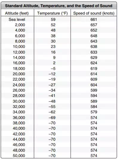
As temperatures fall at higher altitudes, the speed of sound is reduced.
In order to safeguard against these dangers, pilots monitor airspeed closely. A maximum allowable speed is established for the aircraft during certification flight testing. This speed is known the critical Mach number or Mcrit. Mach is a term for the speed of sound. The critical Mach number is expressed as a decimal of Mach such as 0.8 Mach. This means 8 ⁄10 of the speed of sound, regardless of what the actual speed of sound is at any particular altitude.
Many high performance aircraft are equipped with a Machmeter for monitoring Mcrit. The Machmeter is essentially an airspeed instrument that is calibrated in relation to Mach on the dial. Various scales exist for subsonic and supersonic aircraft.
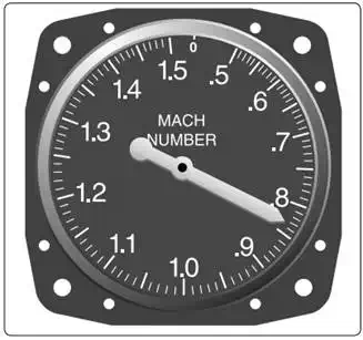
A Machmeter shows the ratio of the speed of sound
In addition to the ram air/ static air diaphragm arrangement, Machmeters also contain an altitude sensing diaphragm. It adjusts the input to the pointer so changes in the speed of sound due to altitude are incorporated into the indication. Some aircraft use a Mach/ airspeed indicator as shown in Figure below.
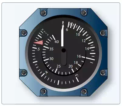
This two-inone instrument contains separate mechanisms to display the airspeed and Mach number. A standard white pointer is used to indicate airspeed in knots against one scale. A red and white striped pointer is driven independently and is read against the Mach number scale to monitor maximum allowable speed.