Altimeters and Altitude
An altimeter is an instrument that is used to indicate the height of the aircraft above a predetermined level, such as sea level or the terrain beneath the aircraft. The most common way to measure this distance is rooted in discoveries made by scientists centuries ago. Seventeenth century work proving that the air in the atmosphere exerted pressure on the things around us led Evangelista Torricelli to the invention of the barometer. Also in that century, using the concept of this first atmospheric air pressure measuring instrument, Blaise Pascal was able to show that a relationship exists between altitude and air pressure. As altitude increases, air pressure decreases. The amount that it decreases is measurable and consistent for any given altitude change. Therefore, by measuring air pressure, altitude can be determined.
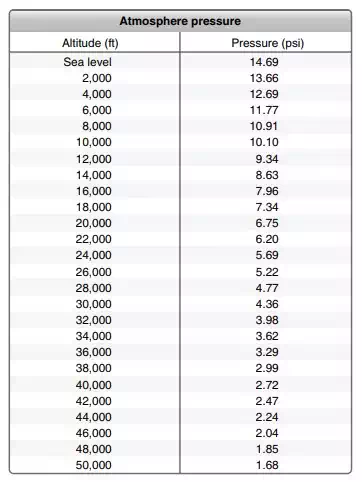
Air pressure is inversely related to altitude. This consistent relationship is used to calibrate the pressure altimeter.
Altimeters that measure the aircraft’s altitude by measuring the pressure of the atmospheric air are known as pressure altimeters. A pressure altimeter is made to measure the ambient air pressure at any given location and altitude. In aircraft, it is connected to the static vent(s) via tubing in the pitot-static system. The relationship between the measured pressure and the altitude is indicated on the instrument face, which is calibrated in feet. These devises are direct-reading instruments that measure absolute pressure. An aneroid or aneroid bellows is at the core of the pressure altimeter’s inner workings. Attached to this sealed diaphragm are the linkages and gears that connect it to the indicating pointer. Static air pressure enters the airtight instrument case and surrounds the aneroid. At sea level, the altimeter indicates zero when this pressure is exerted by the ambient air on the aneroid. As air pressure is reduced by moving the altimeter higher in the atmosphere, the aneroid expands and displays altitude on the instrument by rotating the pointer. As the altimeter is lowered in the atmosphere, the air pressure around the aneroid increases and the pointer moves in the opposite direction.
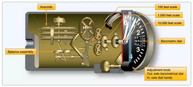
The internal arrangement of a sealed diaphragm pressure altimeter. At sea level and standard atmospheric conditions, the linkage attached to the expandable diaphragm produces an indication of zero. When altitude increases, static pressure on the outside of the diaphragm decreases and the aneroid expands, producing a positive indication of altitude. When altitude decreases, atmospheric pressure increases. The static air pressure on the outside of the diaphragm increases and the pointer moves in the opposite direction, indicating a decrease in altitude.
The face, or dial, of an analog altimeter is read similarly to a clock. As the longest pointer moves around the dial, it is registering the altitude in hundreds of feet. One complete revolution of this pointer indicates 1,000 feet of altitude.
The second-longest point moves more slowly. Each time it reaches a numeral, it indicates 1,000 feet of altitude. Once around the dial for this pointer is equal to 10,000 feet. When the longest pointer travels completely around the dial one time, the second-longest point moves only the distance between two numerals—indicating 1,000 feet of altitude has been attained. If so equipped, a third, shortest or thinnest pointer registers altitude in 10,000 foot increments. When this pointer reaches a numeral, 10,000 feet of altitude has been attained. Sometimes a black-and-white or red-and-white cross-hatched area is shown on the face on the instrument until the 10,000 foot level has been reached.
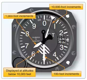
A sensitive altimeter with three pointers and a crosshatched area displayed during operation below 10,000 feet.
Many altimeters also contain linkages that rotate a numerical counter in addition to moving pointers around the dial. This quick reference window allows the pilot to simply read the numerical altitude in feet. The motion of the rotating digits or drum-type counter during rapid climb or descent makes it difficult or impossible to read the numbers. Reference can then be directed to the classic clock-style indication. Figure below illustrates the inner workings behind this type of mechanical digital display of pressure altitude.
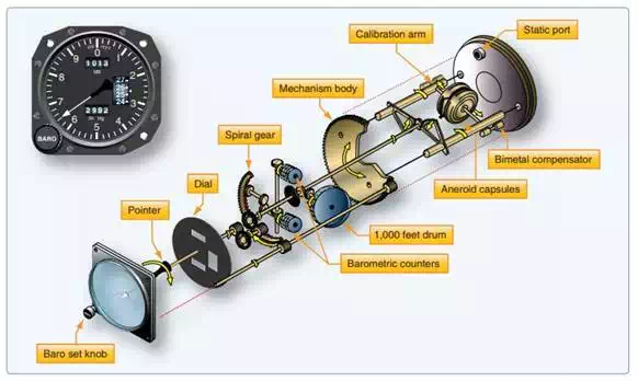
A drum-type counter can be driven by the altimeter’s aneroid for numerical display of altitude. Drums can also be used for the altimeter’s setting indications.
True digital instrument displays can show altitude in numerous ways. Use of a numerical display rather than a reproduction of the clock-type dial is most common. Often a digital numeric display of altitude is given on the electronic primary flight display near the artificial horizon depiction. A linear vertical scale may also be presented to put this hard numerical value in perspective. An example of this type of display of altitude information is shown in Figure below.
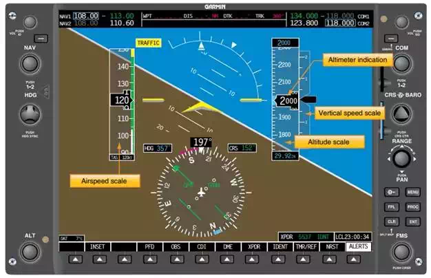
This primary flight display unit of a Garmin 1000 series glass cockpit instrumentation package for light aircraft indicates altitude using a vertical linear scale and a numerical counter. As the aircraft climbs or descends, the scale behind the black numerical altitude readout changes.
Accurate measurement of altitude is important for numerous reasons. The importance is magnified in instrument flight rules (IFR) conditions. For example, avoidance of tall obstacles and rising terrain relies on precise altitude indication, as does flying at a prescribed altitude assigned by air traffic control (ATC) to avoid colliding with other aircraft. Measuring altitude with a pressure measuring device is fraught with complications. Steps are taken to refine pressure altitude indication to compensate for factors that may cause an inaccurate display.
A major factor that affects pressure altitude measurements is the naturally occurring pressure variations throughout the atmosphere due to weather conditions. Different air masses develop and move over the earth’s surface, each with inherent pressure characteristics. These air masses cause the weather we experience, especially at the boundary areas between air masses known as fronts. Accordingly, at sea level, even if the temperature remains constant, air pressure rises and falls as weather system air masses come and go.The values are averages for theoretical purposes.
To maintain altimeter accuracy despite varying atmospheric pressure, a means for setting the altimeter was devised. An adjustable pressure scale visible on the face of an analog altimeter known as a barometric or Kollsman window is set to read the existing atmospheric pressure when the pilot rotates the knob on the front of the instrument. This adjustment is linked through gears inside the altimeter to move the altitude indicating pointers on the dial as well. By putting the current known air pressure (also known as the altimeter setting) in the window, the instrument indicates the actual altitude. This altitude, adjusted for atmospheric pressure changes due to weather and air mass pressure inconsistency, is known as the indicated altitude.
It must be noted that in flight the altimeter setting is changed to match that of the closest available weather reporting station or airport. This keeps the altimeter accurate as the flight progresses.
While there was little need for exact altitude measurement in early fixed wing aviation, knowing one’s altitude provided the pilot with useful references while navigating in the three dimensions of the atmosphere. As air traffic grew and the desire to fly in any weather conditions increased, exact altitude measurement became more important and the altimeter was refined. In 1928, Paul Kollsman invented the means for adjusting an altimeter to reflect variations in air pressure from standard atmospheric pressure. The very next year, Jimmy Doolittle made his successful flight demonstrating the feasibility of instrument flight with no visual references outside of the cockpit using a Kollsman sensitive altimeter.
The
term pressure altitude is used to describe the indication an altimeter gives
when 29.92 is set in the Kollsman window. When flying in U.S. airspace above
18,000 feet mean sea level (MSL), pilots are required to set their altimeters
to 29.92. With all aircraft referencing this standard pressure level, vertical
separation between aircraft assigned to different altitudes by ATC should be
assured. This is the case if all altimeters are functioning properly and pilots
hold their assigned altitudes. Note that the true altitude or actual height of
an aircraft above sea level is only the same as the pressure altitude when
standard day conditions exist. Otherwise, all aircraft with altimeters set to
29.92 "Hg could have true altitudes higher or lower than the pressure
altitude indicated. This is due to the pressure within the air mass in which
they are flying being above or below standard day pressure (29.92). The actual
or true altitude is less important than keeping aircraft from colliding, which
is accomplished by all aircraft above 18,000 feet referencing the same pressure
level (29.92 "Hg)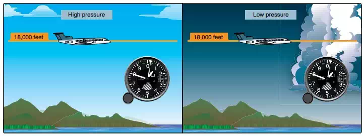
Above 18,000 feet MSL, all aircraft are required to set 29.92 as the reference pressure in the Kollsman window. The altimeter then reads pressure altitude. Depending on the atmospheric pressure that day, the true or actual altitude of the aircraft may be above or below what is indicated (pressure altitude).
Temperature also affects the accuracy of an altimeter. The aneroid diaphragms used in altimeters are usually made of metal. Their elasticity changes as their temperature changes. This can lead to a false indication, especially at high altitudes when the ambient air is very cold. A bimetallic compensating device is built into many sensitive altimeters to correct for varying temperature.
Temperature also affects air density, which has great impact on the performance of an aircraft. Although this does not cause the altimeter to produce an errant reading, flight crews must be aware that performance changes with temperature variations in the atmosphere. The term density altitude describes altitude corrected for nonstandard temperature. That is, the density altitude is the standard day altitude (pressure altitude) at which an aircraft would experience similar performance as it would on the non-standard day currently being experienced. For example, on a very cold day, the air is denser than on a standard day, so an aircraft performs as though it is at a lower altitude. The density altitude is lower that day. On a very hot day, the reverse is true, and an aircraft performs as though it were at a higher elevation where the air is less dense. The density altitude is higher that day.
Conversion factors and charts have been produced so pilots can calculate the density altitude on any particular day. Inclusion of nonstandard air pressure due to weather systems and humidity can also be factored. So, while the effects of temperature on aircraft performance do not cause an altimeter to indicate falsely, an altimeter indication can be misleading in terms of aircraft performance if these effects are not considered.
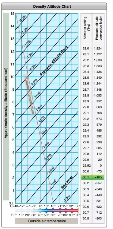
The effect of air temperature on aircraft performance is expressed as density altitude
Other factors can cause an inaccurate altimeter indication. Scale error is a mechanical error whereby the scale of the instrument is not aligned so the altimeter pointers indicate correctly. Periodic testing and adjustment by trained technicians using calibrated equipment ensures scale error is kept to a minimum.
The pressure altimeter is connected to the pitot-static system and must receive an accurate sample of ambient air pressure to indicate the correct altitude. Position error, or installation error, is that inaccuracy caused by the location of the static vent that supplies the altimeter. While every effort is made to place static vents in undisturbed air, airflow over the airframe changes with the speed and attitude of the aircraft. The amount of this air pressure collection error is measured in test flights, and a correction table showing the variances can be included with the altimeter for the pilot’s use. Normally, location of the static vents is adjusted during these test flights so that the position error is minimal. [Figure Below] Position error can be removed by the ADC in modern aircraft, so the pilot need not be concerned about this inaccuracy.
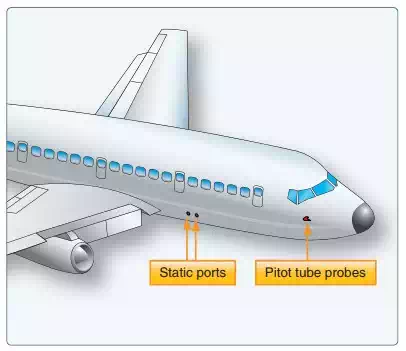
The location of the static vent is selected to keep altimeter position error to a minimum.
Static system leaks can affect the static air input to the altimeter or ADC resulting in inaccurate altimeter indications. It is for this reason that static system maintenance includes leak checks every 24 months, regardless of whether any discrepancy has been noticed. See the instrument maintenance section toward the end of this chapter for further information on this mandatory check. It should also be understood that analog mechanical altimeters are mechanical devices that often reside in a hostile environment. The significant vibration and temperature range swings encountered by the instruments and the pitot static system (i.e., the tubing connections and fittings) can sometime create damage or a leak, leading to instrument malfunction. Proper care upon installation is the best preventive action. Periodic inspection and testing can also insure integrity.
The mechanical nature of the analog altimeter’s diaphragm pressure measuring apparatus has limitations. The diaphragm itself is only so elastic when responding to static air pressure changes. Hysteresis is the term for when the material from which the diaphragm is made takes a set during long periods of level flight. If followed by an abrupt altitude change, the indication lags or responds slowly while expanding or contracting during a rapid altitude change. While temporary, this limitation does cause an inaccurate altitude indication.
It should be noted that many modern altimeters are constructed to integrate into flight control systems, autopilots, and altitude monitoring systems, such as those used by ATC. The basic pressure-sensing operation of these altimeters is the same, but a means for transmitting the information is added.