Boundary Layer Separation and Pressure Drag
At the start of the 19th century, after studying the highly cambered
thin wings of many different birds, Sir George Cayley designed and built the
first modern aerofoil, later used on a hand-launched glider. This biomimetic,
highly cambered and thin-walled design remained the predominant aerofoil shape
for almost 100 years, mainly due to the fact that the actual mechanisms of lift
and drag were not understood scientifically but were explored in an empirical
fashion. One of the major problems with these early aerofoil designs was that
they experienced a phenomenon now known as boundary layer separation at
very low angles of attack. This significantly limited the amount of lift that
could be created by the wings and meant that bigger and bigger wings were needed
to allow for any progress in terms of aircraft size. Lacking the analytical
tools to study this problem, aerodynamicists continued to advocate thin
aerofoil sections, as there was plenty of evidence in nature to suggest their
efficacy. The problem was considered to be more one of degree, i.e.
incrementally iterating the aerofoil shapes found in nature, rather than of
type, that is designing an entirely new shape of aerofoil in accord with
fundamental physics.
During the pre-WWI era, the misguided notions of designers was
compounded by the ever-increasing use of wind-tunnel tests. The wind tunnels
used at the time were relatively small and ran at very low flow speeds. This
meant that the performance of the aerofoils was being tested under the
conditions of laminar flow (smooth flow in layers, no mixing perpendicular to
flow direction) rather than the turbulent flow (mixing of flow via small
vortices) present over the wing surfaces. Under laminar flow conditions,
increasing the thickness of an aerofoil increases the amount of skin-friction
drag (as shown in last month’s post), and hence thinner aerofoils were
considered to be superior.
The modern plane – born in 1915
The situation in Germany changed dramatically during WWI. In 1915 Hugo
Junkers pioneered the first practical all-metal aircraft with a cantilevered
wing – essentially the same semi-monocoque wing
box design used today. The most popular design up to then was the
biplane configuration held together by wires and struts, which introduced
considerable amounts of parasitic drag and thereby limited the maximum speed of
aircraft. Eliminating these supporting struts and wires meant that the flight
loads needed to be carried by other means. Junkers cantilevered a beam from
either side of the fuselage, the main spar, at about 25% of the chord of the
wing to resist the up and down bending loads produced by lift. Then he fitted a
smaller second spar, known as the trailing edge spar, at 75% of the chord to
assist the main spar in resisting fore and aft bending induced by the drag on
the wing. The two spars were connected by the external wing skin to produce a
closed box-section known as the wing box. Finally, a curved piece of metal was
fitted to the front of the wing to form the “D”-shaped leading edge, and two
pieces of metal were run out to form the trailing edge. This series of three
closed sections provided the wing with sufficient torsional rigidity to sustain
the twisting loads that arise because the aerodynamic centre (the point where
the lift force can be considered to act) is offset from the shear centre (the
point where a vertical load will only cause bending and no twisting). Junker’s
ideas were all combined in the world’s first practical all-metal aircraft, the
Junker J 1, which although much heavier than other aircraft at the time,
developed into the predominant form of construction for the larger and faster
aircraft of the coming generation.
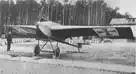
Junkers J 1 at Döberitz in
1915
Structures + Aerodynamics = Superior
Aircraft
Junkers construction naturally resulted in a much thicker wing due to
the room required for internal bracing, and this design provided the impetus
for novel aerodynamics research. Junker’s ideas were supported by Ludwig Prandtl who carried out his famous aerodynamics work
at the University of Göttingen. As discussed
in last month’s post, Prandtl had
previously introduced the notion of the boundary layer; namely the existence of
a U-shaped velocity profile with a no-flow condition at the surface and an
increasing velocity field towards the main stream some distance away from the
surface. Prandtl argued that the presence
of a boundary layer supported the simplifying assumption that fluid flow can be
split into two non-interacting portions; a thin layer close to the surface
governed by viscosity (the stickiness of the fluid) and an inviscid mainstream.
This allowed Prandtl and his colleagues to
make much more accurate predictions of the lift and drag performance of
specific wing-shapes and greatly helped in the design of German WWI aircraft.
In 1917 Prandtl showed that Junker’s thick
and less-cambered aerofoil section produced much more favourable lift
characteristics than the classic thinner sections used by Germany’s enemies.
Second, the thick aerofoil could be flown at a much higher angle of attack
without stalling and hence improved the manoeuvrability of a plane during dog
fighting.
Skin Friction versus Pressure Drag
The flow in a boundary layer can be either laminar or turbulent. Laminar
flow is orderly and stratified without interchange of fluid particles between
individual layers, whereas in turbulent flow there is significant exchange of
fluid perpendicular to the flow direction. The type of flow greatly influences
the physics of the boundary layer. For example, due to the greater extent of
mass interchange, a turbulent boundary layer is thicker than a laminar one and
also features a steeper velocity gradient close to the surface, i.e. the flow
speed increases more quickly as we move away from the wall.
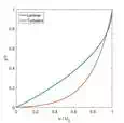
Velocity
profile of laminar versus turbulent boundary layer. Note how the turbulent flow
increases velocity more rapidly away from the wall.
Just like your hand experiences friction when sliding over a surface, so
do layers of fluid in the boundary layer, i.e. the slower regions of the flow
are holding back the faster regions. This means that the velocity gradient
throughout the boundary layer gives rise to internal shear stresses that are
akin to friction acting on a surface. This type of friction is aptly
called skin-friction drag and is predominant in streamlined
flows where the majority of the body’s surface is aligned with the flow. As the
velocity gradient at the surface is greater for turbulent than laminar flow, a
streamlined body experiences more drag when the boundary layer flow over its
surfaces is turbulent. A typical example of a streamlined body is an aircraft
wing at cruise, and hence it is no surprise that maintaining laminar flow over
aircraft wings is an ongoing research topic.
Over flat surfaces we can suitably ignore any changes in pressure in the
flow direction. Under these conditions, the boundary layer remains stable but
grows in thickness in the flow direction. This is, of course, an idealised
scenario and in real-world applications, such as curved wings, the flow is most
likely experiencing an adverse pressure gradient, i.e. the pressure increases
in the flow direction. Under these conditions the boundary layer can become
unstable and separate from the surface. The boundary layer separation induces a
second type of drag, known as pressure drag. This type of drag is
predominant for non-streamlined bodies, e.g. a golfball flying
through the air or an aircraft wing at a high angle of attack.
So why does the flow separate in the first
place?
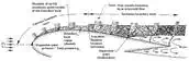
To answer this question consider fluid flow over a cylinder. Right at
the front of the cylinder fluid particles must come to rest. This point is
aptly called the stagnation point and is the point of maximum pressure (to
conserve energy the pressure needs to fall as fluid velocity increases, and
vice versa). Further downstream, the curvature of the cylinder causes the flow
lines to curve, and in order to equilibrate the centripetal forces, the
flow accelerates and the fluid pressure drops. Hence, an area of accelerating
flow and falling pressure occurs between the stagnation point and the poles of
the cylinder. Once the flow passes the poles, the curvature of the cylinder is
less effective at directing the flow in curved streamlines due to all the open
space downstream of the cylinder. Hence, the curvature in the flow reduces and
the flow slows down, turning the previously favourable pressure gradient into
an adverse pressure gradient of rising pressure.

Boundary layer separation over a cylinder (axis out out the page).
To understand boundary layer separation we need to understand how these
favourable and adverse pressure gradients influence the shape of the boundary
layer. From our discussion on boundary layers, we know that the fluid travels
slower the closer we are to the surface due to the retarding action of the
no-slip condition at the wall. In a favourable pressure gradient, the falling
pressure along the streamlines helps to urge the fluid along, thereby
overcoming some of the decelerating effects of the fluid’s viscosity. As a
result, the fluid is not decelerated as much close to the wall leading to a
fuller U-shaped velocity profile, and the boundary layer grows more slowly.
By analogy, the opposite occurs for an adverse pressure gradient, i.e.
the mainstream pressure increases in the flow direction retarding the flow in
the boundary layer. So in the case of an adverse pressure gradient the pressure
forces reinforce the retarding viscous friction forces close to the surface. As
a result, the difference between the flow velocity close to the wall and the
mainstream is more pronounced and the boundary layer grows more quickly. If the
adverse pressure gradient acts over a sufficiently extended distance, the
deceleration in the flow will be sufficient to reverse the direction of
flow in the boundary layer. Hence the boundary layer develops a point of
inflection, known as the point of boundary layer separation, beyond
which a circular flow pattern is established.
For aircraft wings, boundary layer separation can lead to very
significant consequences ranging from an increase in pressure drag to a
dramatic loss of lift, known as aerodynamic stall. The shape of an aircraft
wing is essentially an elongated and perhaps asymmetric version of the cylinder
shown above. Hence the airflow over the top convex surface of a wing follows
the same basic principles outlined above:
● There is a point of stagnation at the leading edge.
● A region of accelerating mainstream flow (favourable pressure gradient)
up to the point of maximum thickness.
● A region of decelerating mainstream flow (adverse pressure gradient)
beyond the point of maximum thickness.
These three points are summarised in the schematic diagram below.
Boundary layer separation over the top surface of a wing.
Boundary layer separation is an important issue for aircraft wings as it
induces a large wake that completely changes the flow downstream of the point
of separation. Skin-friction drag arises due to inherent viscosity of the
fluid, i.e. the fluid sticks to the surface of the wing and the associated
frictional shear stress exerts a drag force. When a boundary layer separates, a
drag force is induced as a result of differences in pressure upstream and
downstream of the wing. The overall dimensions of the wake, and therefore the
magnitude of pressure drag, depends on the point of separation along the wing.
The velocity profiles of turbulent and laminar boundary layers (see image
above) show that the velocity of the fluid increases much slower away from the
wall for a laminar boundary layer. As a result, the flow in a laminar boundary
layer will reverse direction much earlier in the presence of an adverse
pressure gradient than the flow in a turbulent boundary layer.
To summarise, we now know that the inherent viscosity of a fluid leads
to the presence of a boundary layer that has two possible sources of drag.
Skin-friction drag due to the frictional shear stress between the fluid and the
surface, and pressure drag due to flow separation and the existence of a
downstream wake. As the total drag is the sum of these two effects, the
aerodynamicist is faced with a non-trivial compromise:
● skin-friction drag is reduced by laminar flow due to a lower shear stress at the
wall, but this increases pressure drag when boundary layer separation occurs.
● pressure drag
is reduced by turbulent flow by delaying boundary layer separation, but this
increases the skin-friction drag due to higher shear stresses at the wall.
As a result, neither laminar nor turbulent flow can be said to be
preferable in general and judgement has to be made regarding the specific
application. For a blunt body, such as a cylinder, pressure drag dominates and
therefore a turbulent boundary layer is preferable. For more streamlined
bodies, such as an aircraft wing at cruise, the overall drag is dominated by
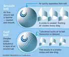
skin-friction drag and hence a laminar boundary layer is preferable. Dolphins,
for example, have very streamlined bodies to maintain laminar flow. Early
golfers, on the other hand, realised that worn rubber golf balls flew further
than pristine ones, and this led to the innovation of dimples on golf balls.
Fluid flow over golf balls is predominantly laminar due to the relatively low
flight speeds. Dimples are therefore nothing more than small imperfections that
transform the predominantly laminar flow into a turbulent one that delays the
onset of boundary layer separation and therefore reduces pressure drag.
Aerodynamic Stall
The second, and more dramatic effect, of boundary layer separation in
aircraft wings is aerodynamic stall. At relatively low angles of attack, for
example during cruise, the adverse pressure gradient acting on the top surface
of the wing is benign and the boundary layer remains attached over the entire
surface. As the angle of attack is increased, however, so does the pressure
gradient. At some point the boundary layer will start to separate near the
trailing edge of the wing, and this separation point will move further upstream
as the angle of attack is increased. If an aerofoil is positioned at a
sufficiently large angle of attack, separation will occur very close to the
point of maximum thickness of the aerofoil and a large wake will develop behind
the point of separation. This wake redistributes the flow over the rest of the
aerofoil and thereby significantly impairs the lift generated by the wing. As a
result, the lift produced is seriously reduced in a condition known as aerodynamic
stall. Due to the high pressure drag induced by the wake, the aircraft can
further lose airspeed, pushing the separation point further upstream and creating
a deleterious feedback loop where the aircraft literally starts to fall out of
the sky in an uncontrolled spiral. To prevent total loss of control, the pilot
needs to reattach the boundary as quickly as possible which is achieved by
reducing the angle of attack and pointing the nose of the aircraft down to gain
speed.
The lift produced by a wing is given by
![]()
where ![]() is
the density of the surrounding air,
is
the density of the surrounding air, ![]() is
the flight velocity,
is
the flight velocity, ![]() is
the wing area and
is
the wing area and ![]() is
the lift coefficient of the aerofoil shape. The lift coefficient of a specific
aerofoil shape increases linearly with the angle of attack up to a
maximum point
is
the lift coefficient of the aerofoil shape. The lift coefficient of a specific
aerofoil shape increases linearly with the angle of attack up to a
maximum point ![]() . The maximum lift coefficient
of a typical aerofoil is around 1.4 at an angle of attack of around
. The maximum lift coefficient
of a typical aerofoil is around 1.4 at an angle of attack of around ![]() , which
is bounded by the critical angle of attack where the stall condition occurs.
, which
is bounded by the critical angle of attack where the stall condition occurs.
During cruise the angle of attack is relatively small (![]() ) as
sufficient lift is guaranteed by the high flight velocity
) as
sufficient lift is guaranteed by the high flight velocity ![]() . Furthermore, we actually want to maintain a small angle of
attack as this minimises the pressure drag induced by boundary layer
separation. At takeoff and landing,
however, the flight velocity is much smaller which means that the lift
coefficient has to be increased by setting the wings at a more aggressive angle
of attack (
. Furthermore, we actually want to maintain a small angle of
attack as this minimises the pressure drag induced by boundary layer
separation. At takeoff and landing,
however, the flight velocity is much smaller which means that the lift
coefficient has to be increased by setting the wings at a more aggressive angle
of attack (![]() ). The
issue is that even with a near maximum lift coefficient of 1.4, large jumbo
jets have a hard time achieving the necessary lift force at safe speeds for
landing. While it would also be possible to increase the wing area, such a
solution would have detrimental effect on the aircraft weight and therefore
fuel efficiency.
). The
issue is that even with a near maximum lift coefficient of 1.4, large jumbo
jets have a hard time achieving the necessary lift force at safe speeds for
landing. While it would also be possible to increase the wing area, such a
solution would have detrimental effect on the aircraft weight and therefore
fuel efficiency.
High-lift Devices
A much more elegant solution are leading-edge slats and trailing-edge
flaps. A slat is a thin, curved aerofoil that is fitted to the front of the
wing and is intended to induce a secondary airflow through the gap between the
slat and the leading edge. The air accelerates through this gap and thereby
injects high momentum fluid into the boundary on the upper surface, delaying
the onset of flow reversal in the boundary layer. Similarly, one or two curved
aerofoils may be placed at the rear of wing in order to invigorate the flow
near the trailing edge. In this case the high momentum fluid reinvigorates the
flow which has been slowed down by the adverse pressure gradient. The maximum
lift coefficient can typically be doubled by these devices and therefore allows
big jumbo jets to land and takeoff at
relatively low runway speeds.
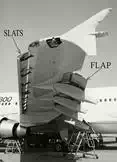
Leading edge slats and trailing edge flaps on an aircraft
wing
The next time you are sitting close to the wings observe how these
devices are retracted after take-off and activated before landing. In fact,
birds have a similar devices on their wings. The wings of bats are comprised of
thin and flexible membranes reinforced by small bones which roughen the
membrane surface and help to transition the flow from laminar to turbulent and
prevent boundary layer separation. As is so often the case in engineering design,
a lot of inspiration can be taken from nature!
Smart
Materials Application: Variable Geometry Chevron for Noise Reduction
For many years engineers have been trying to harness mechanical work
from thermal energy by taking advantage of the crystallographic phase change
of shape memory alloys (SMA’s). SMA’s can exhibit strains of
up to 8% actuated by a transformation of the internal crystal structure
from martensite to austenite as the metal
is heated. This solid state phase change causes a shearing of the internal
structure that deforms the material. By introducing additional internal
stresses the alloy can be “trained” to transition between two states by
applying temperature changes. One of the most well-known projects of the past
is the Smart Aircraft and Marine Propulsion System demonstration
(SAMPSON), intending to demonstrate the potential of SMA’s in tailoring the
geometry of jet-propulsion systems through a series of experiments.

Boeing variable geometry chevron, flight testing (1)
One experiment investigated the utilisation of bending actuation of
SMA’s to optimise the compromise between noise-mitigation at take-off and
landing (noise levels are strictly regulated by civil agencies), and maximum
thrust at cruise altitude. To achieve this Boeing formed the trailing edge of
the exhaust nozzles on commercial turbo-fat jet engines in a triangular
“chevron” shape (Figure 1) designed to be reconfigurable by actuation of
embedded SMA beam components. The “Variable Geometry Chevrons” (Figure
2) feature NiTi (60% Ni and 40% Ti by weight) SMA beam elements encased in the
composite chevrons in a complex 3-D configuration to induce the necessary
bending moments to force the chevrons inwards into the bypass flow at low
altitudes and low speeds where the engine temperature is high. The intruding
chevrons cause a disturbance in the bypass flow, inducing a broader diffusion
and mixing of the hot exhaust gases with the cooler bypass flow. Thereby the
shear stress between the two different-velocity flows is decreased leading to a
reduction in the noise level.

FEA analysis of Boeing Variable Geometry Chevron with SMA
strips shown (1)
At higher altitudes and high speeds where the engine temperature is low,
the chevrons relax and straighten-out. This guarantees a smooth exit flow that
decreases the pressure difference between the inlet and exit of the engine and
thus increases the engine thrust. In the original work published by Mabe et al. (2005) the system is designed for both
autonomous operation as well as controlled actuation using heaters installed in
the engine casing with a closed loop controller to maintain optimum in-flight
tip immersions. A parametric study showed that during cruise marginal immersion
helped to reduce shock cell noise with negligible thrust penalty.
NASA developed an active bending chevron system by embedding tensile
pre-stressed NiTinol SMA strips on one side of the neutral axis of the composite
laminate. Actively controlled thermal excitation thus causes the SMA actuators
to attempt recovery of the pre-strain constrained by the bond to the host
material. The resulting asymmetry in thermal stress causes a moment
that deflects the structure. The aerodynamic load due to engine flow
and the strain energy stored in the deformed host composite are used to restore
the structure to the un-actuated configuration.
The simple design appeals by its lightweight construction with low part
count and opportunity to be fully integrated into an autonomous morphing
system. The “Variable Geometry Chevron” demonstrates the excellent
potential of SMA’s to be integrated in composite laminates to provide internal
actuation for smart structures.