Flight dynamics - Detail
Flight
dynamics is
the science of air and space vehicle
orientation and control in three dimensions. The three critical flight dynamics
parameters are the angles of rotation in three dimensions about the
vehicle's center of mass, known as pitch, roll and yaw (quite
different from their use as Tait-Bryan angles).

Aerospace
engineers develop control systems for a vehicle's orientation (attitude) about
its center of mass. The control systems
include actuators, which exert forces in various directions, and generate
rotational forces or moments about the aerodynamic center of
the aircraft, and thus rotate the aircraft in pitch, roll, or yaw. For example,
a pitching moment is a vertical force applied at a distance forward or aft from
the aerodynamic center of the aircraft,
causing the aircraft to pitch up or down.
Roll, pitch and
yaw refer to rotations about the respective axes starting from a defined
equilibrium state. The equilibrium roll angle is known as wings level or zero
bank angle, equivalent to a level heeling angle on a ship. Yaw is known as
'heading'. The equilibrium pitch angle in submarine and airship parlance is
known as 'trim', but in aircraft, this usually refers to angle of attack,
rather than orientation. However, common usage ignores this distinction between
equilibrium and dynamic cases.
The most common
aeronautical convention defines the roll as acting about the longitudinal axis,
positive with the starboard(right) wing down. The
yaw is about the vertical body axis, positive with the nose to starboard. Pitch
is about an axis perpendicular to the longitudinal plane of symmetry, positive
nose up.
A fixed-wing
aircraft increases or decreases the lift generated by the wings when it pitches
nose up or down by increasing or decreasing the angle of attack (AOA). The roll
angle is also known as bank angle on a fixed wing aircraft, which usually
"banks" to change the horizontal direction of flight. An aircraft is
usually streamlined from nose to tail to reduce drag making it typically
advantageous to keep the sideslip angle near zero, though there are instances
when an aircraft may be deliberately "sideslipped"
for example a slip in a fixed wing aircraft.
Coordinate systems
The position
(and hence motion) of an aircraft is generally defined relative to one of 3
sets of co-ordinate systems:
● Wind Axes
● X Axis - Positive in the
direction of the oncoming air (relative wind)
● Y Axis - Positive to Right
of X Axis, perpendicular to X Axis
● Z Axis - Positive downwards, perpendicular to X-Y plane
● Inertial Axes (or Body
Axes) - based about aircraft CG
● X Axis - Positive forward,
through nose of aircraft
● Y Axis - Positive to Right
of X Axis, perpendicular to X Axis
● Z Axis - Positive downwards, perpendicular to X-Y plane
● Earth Axes
● X Axis - Positive in the
direction of North
● Y Axis - Positive in the
direction of East (perpendicular to X Axis)
● Z Axis - Positive towards
the centre of Earth (perpendicular to X-Y Plane)
For flight
dynamics applications the Earth Axes are generally of minimal use, and hence
will be ignored. The motions relevant to dynamic stability are usually too
short in duration for the motion of the Earth itself to be considered relevant
for aircraft.
In flight
dynamics, pitch, roll and yaw angles measure both the absolute attitude angles
(relative to the horizon/North) and changes in attitude
angles, relative to the equilibrium orientation of the vehicle. These are
defined as:
● Pitch - Angle of X Body
Axis (nose) relative to horizon. Also a positive (nose up) rotation about Y
Body Axis
● Roll - Angle of Y Body Axis
(wing) relative to horizon. Also a positive (right wing down) rotation about X
Body Axis
● Yaw - Angle of X Body Axis
(nose) relative to North. Also a positive (nose right) rotation about Z Body
axis
In analysing the
dynamics, we are concerned both with rotation and translation of this axis set
with respect to a fixed inertial frame. For all practical purposes a local
Earth axis set is used, this has X and Y axis in the local horizontal plane,
usually with the x-axis coinciding with the projection of the velocity vector
at the start of the motion, on to this plane. The z axis is vertical, pointing
generally towards the Earth's centre, completing an orthogonal set.
In general, the
body axes are not aligned with the Earth axes. The body orientation may be
defined by three Euler angles, the Tait-Bryan rotations, a quaternion, or a
direction cosine matrix (rotation matrix). A rotation matrix is particularly
convenient for converting velocity, force, angular velocity, and torque vectors
between body and Earth coordinate frames.
Body axes tend
to be used with missile and rocket configurations. Aircraft stability uses wind
axes in which the x-axis points along the velocity vector. For straight and
level flight this is found from body axes by rotating nose down through the
angle of attack.
Stability deals
with small perturbations in angular displacements about the orientation at the
start of the motion. This consists of two components; rotation about each axis,
and angular displacements due change in orientation of each axis. The latter
term is of second order for the purpose of stability analysis, and is ignored.
Design cases
In analysing the
stability of an aircraft, it is usual to consider perturbations about a nominal
equilibrium position. So the analysis would be applied, for example, assuming:
Steady
level flight
Turn
at constant speed
Approach
and landing
Take
off
The speed,
height and trim angle of attack are different for each flight condition, in
addition, the aircraft will be configured differently, e.g. at low speed flaps
may be deployed and the undercarriage may be down.
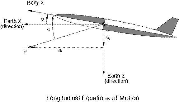
Except for
asymmetric designs (or symmetric designs at significant sideslip), the
longitudinal equations of motion (involving pitch and lift forces) may be
treated independently of the lateral motion (involving roll and yaw).
The following
considers perturbations about a nominal straight and level flight path.
To keep the
analysis (relatively) simple, the control surfaces are assumed fixed throughout
the motion, this is stick-fixed stability. Stick-free analysis requires the
further complication of taking the motion of the control surfaces into account.
Furthermore, the
flight is assumed to take place in still air, and the aircraft is treated as a
rigid body.
Spacecraft
Unless designed
to conduct part of the mission within a planetary atmosphere, a spacecraft
would generally have no discernible front or side, and no bottom unless
designed to land on a surface, so reference to a 'nose' or 'wing' or even
'down' is arbitrary. On a manned spacecraft, the axes must be oriented relative
to the pilot's physical orientation at the flight control station. Unmanned
spacecraft may need to maintain orientation of solar cells toward the Sun,
antennas toward the Earth, or cameras toward a target, so the axes will
typically be chosen relative to these functions.
Longitudinal modes
It is common
practice to derive a fourth order characteristic equation to describe the
longitudinal motion, and then factorise it approximately into a high frequency
mode and a low frequency mode. This requires a level of algebraic manipulation
which most readers will doubtless find tedious, and adds little to the
understanding of aircraft dynamics. The approach adopted here is to use our
qualitative knowledge of aircraft behaviour to simplify the equations from the
outset, reaching the same result by a more accessible route.
The two
longitudinal motions (modes) are called the short period pitch oscillation
(SSPO), and the phugoid.
Short-period pitch oscillation
A short input
(in control systems terminology an impulse) in pitch (generally via the
elevator in a standard configuration fixed wing aircraft) will generally lead
to overshoots about the trimmed condition. The transition is characterised by a
damped simple harmonic motion about the new trim. There is very little change
in the trajectory over the time it takes for the oscillation to damp out.
Generally this
oscillation is high frequency (hence short period) and is damped over a period
of a few seconds. A real-world example would involve a pilot selecting a new
climb attitude, for example 5º nose up from the original attitude. A short,
sharp pull back on the control column may be used, and will generally lead to
oscillations about the new trim condition. If the oscillations are poorly
damped the aircraft will take a long period of time to settle at the new
condition, potentially leading to Pilot-induced oscillation. If the short
period mode is unstable it will generally be impossible for the pilot to safely
control the aircraft for any period of time.
This
damped harmonic motion is called the short period pitch oscillation, it arises
from the tendency of a stable aircraft to point in the general direction of
flight. It is very similar in nature to the weathercock mode of missile or
rocket configurations. The motion involves mainly the pitch attitude θ (theta)
and incidence α (alpha). The direction of the
velocity