Design of Jet Engines
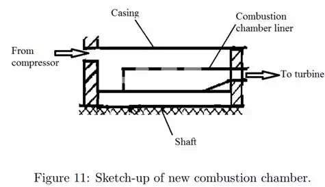
Figure 10 shows the first design. It was made by analyzing common jet engines and figuring out the most suitable design for this project. The design consists of a radial compressor, an annular combustion chamber and an axial turbine. Due to the changes along the way, the original design was altered. Some materials that were ordered was not delivered and had to be replaced by material available in the workshop. The changes are mainly in the combustion chamber, where instead of air from the compressor flowing both inside and outside the combustion liner it now only flows outside and the tube around the shaft forms the inside of the combustion chamber. A quick sketch-up of this is in figure 11 The outer casing now also goes over the turbine plate instead of being fitted in a notch cut in the plate.
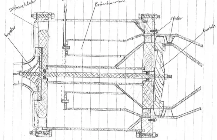
Figure 10: First design.
Construction
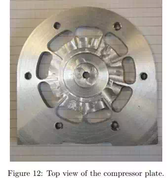
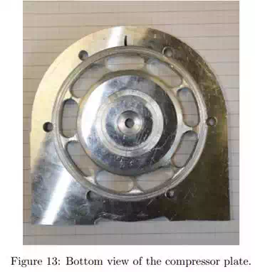
The compressor plate is shown in figures 12 and 13. The plate is made from aluminium and is attached to the front of the housing. Milling was used to create a recess in the middle of the plate to house the compressor, and a hole for the shaft was drilled through. The guide vanes were milled to redirect the swirling air from the compressor outwards, for simplicity they were made radial, although for the best flow they should start tangential to the flow and form a smooth diffusor. A circle of ducts through the plate were milled for the air to pass to the combustion chamber. Holes for screws were made at the outer edge to be able to attach to the housing. On the back side, tracks were lathed to fit the housing and the inner pipe.
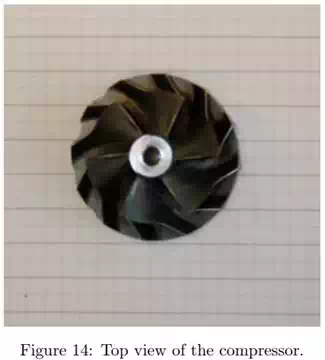
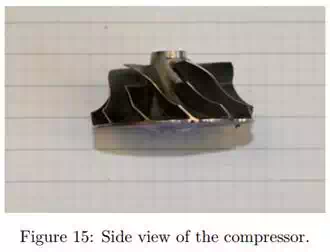
The compressor used in the engine is shown in Figures 14 and 15. It is a centrifugal compressor, with backward-facing vanes, originally from a turbocharger used in an automotive engine. This was later found to be incompatible with the rest of the design since it did not provide enough compression at the speeds.
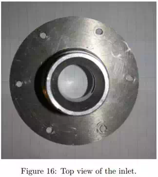
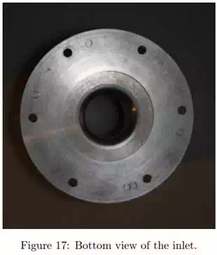
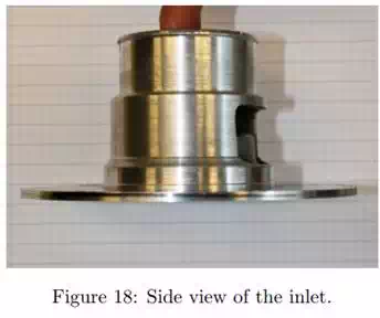
The inlet of the engine is shown from different angles in Figures 16, 17 and 18. The top piece is taken from the inlet housing of a turbocharger, which is the same turbocharger that the compressor came from. It was used to give a good fit between the inlet and the compressor. The inlet piece was lathed round and then shrink-fitted to a round aluminum plate. Holes where then drilled along the edge for screws to go through the compressor plate and attach to the housing.
The housing of the engines is shown from different angles in Figures 19, 20 and 21. The housing is made of steel and mounts where welded to the outside, holes where drilled to attach the inlet and compressor plate. The diameter of the housing was choosen when the engine was designed. It was considered to be a reasonable size. At the inside of the housing, the turbine plate is seen. This is made from aluminum and is designed to give a firm structure and to make sure no air escapes at the inside of the housing, from elsewhere than the turbine outlet. The turbine plate is shrinkfitted and made to let the hot gas pass from the combustion chamber onto the turbine blades, which are located just behind the turbine plate. The front side of the turbine plate was lathed to hold the combustion chamber in place.
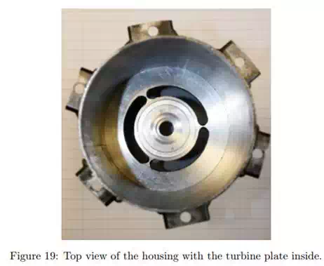
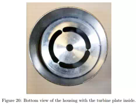
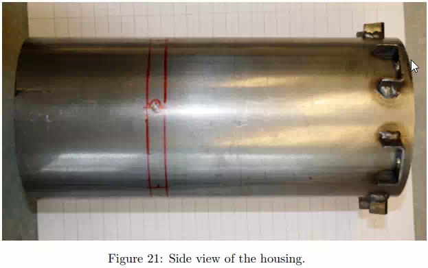
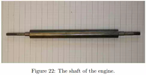
Figure 22 shows the steel shaft of the engine. The length of the shaft was determined after calculations on a suitable length of the combustion chamber, which is the space between the compressor plate and turbine plate. The top and the bottom of the shaft was threaded with a thread-die, to hold the compressor and the turbine in place with a nut at each side. Both the compressor and the turbine was pushed into a heel at the shaft with help of the nut to stay in place. The bearings were pushed into place with a heel at the shaft, and a heel at the plate. The inner rotating part of the bearing was held by a heel at the shaft, and the outer stationary part was held by a heel at the plate. Using this design, the length of the shaft and the distance to the heels would hold the bearings in place when the engine is assembled. The diameter at the top and at the bottom of the shaft was determined by the inner diameter of the bearing.
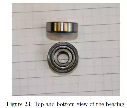
The two bearings used in the engine are shown in figure 23. The bearings are located in the compressor plate and in the turbine plate, where they fit in a lathed hole. Punchmarks on the side of the plates and cylindrical glue help to keep the bearings in place. They allign the shaft at the center of the engine and provide stability.
The most common combustion chamber is the annular type, and it is chosen for this project. This type has a more evenly distributed combustion, compared to can and can-annular, since it takes place in a more spacious environment. It is also more efficient than the previous types.
The holes for air distribution was determined with respect to the area of the inlet. The first two rows of holes with radius of 4 mm covered an area of 26 % of the total area of the inlet, which is called the primary zone. The remaining holes of 8 mm and 13 mm where calculated to covered an area of 57 % of the total inlet area, which is called the dilution zone. The holes were made to give the correct dilution, and distribution of the air.
The combustion chamber is made from two pipes of different diameter and the combustion liner, which is the biggest pipe, is shown in figure 24 and 25. The shaft is located at the center of the chamber. Typical value of length to diameter for liners ranges from three to six. The diameter of the pipes was set when the design was made, so the length was set within the range.The combustion liner structure is made from steel, and the end of the chamber was lathed to fit the outside duct liner in the turbine plate.
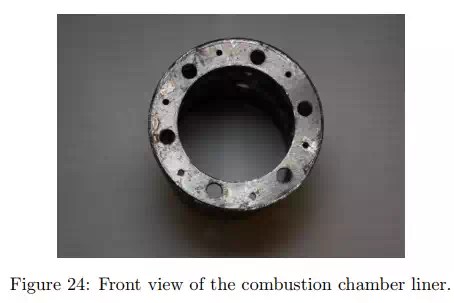
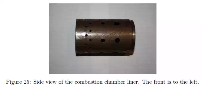
Figure 26 shows the fuel line. It is made from copper and is formed to sit at the front of the combustion liner. The brass pieces silver soldered on the fuel line are nozzles that protrude into the combustion chamber.
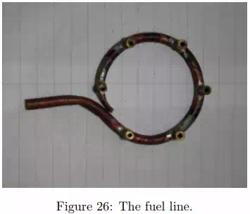
Figure 27 and 28 show the inside liner forming a duct from the the combustion chamber to the turbine. Due to that the turbine plate was made from aluminium, steel was needed as a protective coating. The coating is located at the end of the chamber, just before the turbine plate
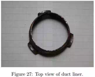
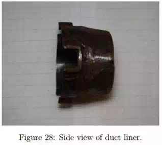
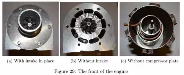
Figure 29(a) shows the assembled engine from the front. The intake is removed in figure 29(b), showing the compressor resting on the compressor plate. The compressor plate is removed in figure 29(c), showing the fuel line resting on the combustion chamber.