Combustion chamber
In the combustion chamber is where the combustion takes place. Here, heat is added to the jet engine in the Brayton Cycle. Compressed air flows from the compressor into the chamber and ignites after being mixed with the fuel. The efficiency of the combustion is given by
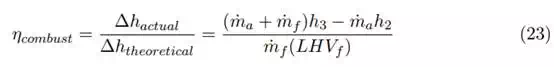
m˙ air mass flow of gas
m˙ fuel mass flow of fuel
h3 enthalpy of gas after combustor
h2 enthalpy of gas before combustor
LHV fuel heating value
The actual change of enthalpy in the chamber is given by ∆hactual and is divided by the theoretical change of enthalpy, ∆htheoretical, given by the energy added by the fuel. For this formula we assume an adiabatic process where no heat flows through the boundary of the chamber ∆Q = 0.
The efficiency given is to see how much of the fuel that takes part in the combustion. Fuel that is unburned is wasted and therefore reduces the efficiency. A major problem in maintaining a high efficiency is loss of pressure. In an ideal Brayton cycle the pressure is kept at a constant level through the combustion chamber. But with pressure losses from such things as wall friction, turbulence and heat loss, it is not possible. There are three stages in the combustion chamber. The recirculation zone, the burning zone and the dilution zone. Here the fuel gets, respectively, evaporated and partially burned, and then completely burned, and last mixed with bypass air to provide proper cooling. About 25% to 35% of the incoming air is entered directly into the flame tube, where the combustion takes place. The rest of the air is bypassed and used for cooling of the housing and to keep a steady flame. An important part of the chamber is the diffuser, located before the liner, which is used to slow the compressed air down to a speed better suited for combustion. In addition to the diffuser the bypassed air is also used to create turbulence in the liner which also slows the flow.
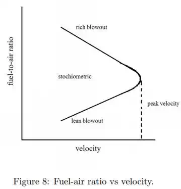
Figure 8 shows how the velocity of the gas relates to the fuel-air ratio, this shows the important of velocity for a good combustion and also that there is an upper limit. A high velocity and a high fuel-air ratio will give a rich blowout. Which means that oxygen is displaced by fuel, which lowers the temperature of the flame and in some cases distinguishes it. A lean blowout is where not enough fuel is given to the flame and could also cause it to be distinguished, this is also used for lowering the engine RPM. The peak velocity and optimal fuel-air ratio gives the best combustion. Fuel-air ratio when burning propane, which is the fuel chosen for this project, is approximately 1 kg propane per 12 m3 of air.
Different from an internal combustion engine, in which ignition is needed at every cycle, the jet engine works with a continuous flow. The igniter needs only to create a spark at the start-up. Once the air and fuel-mixture has been ignited the combustion will be self-sustained. There are three different types of combustion chambers used in aircrafts. Annular, can and can-annular, as shown in cross-section in figure 9. All three types have the same function, to increase the temperature of the high-pressure gas. The combustion chamber used for this project is the annular combustion chamber.
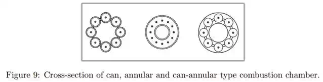
Can and can-annular work in similar ways. The combustion takes place in several cans, placed symmetrically around the shaft. The difference lies in the forming casing. The can-annular has a more evenly structure, keeping the cans together. While the can type is kept together by a ring-type structure.
The annular combustion chamber is the most common type. It is the most efficient of the three and has the simplest structure.