Exhaust Gas Flow
Gas from the engine turbine enters the exhaust system at velocities from 750 to 1,200 feet per second, but, because velocities of this order produce high friction losses, the speed of flow is decreased by diffusion. This is accomplished by having an increasing passage area between the exhaust cone and the outer wall as shown in fig. 6-1. The cone also prevents the exhaust gases from flowing across the rear face of the turbine disc. It is usual to hold the velocity at the exhaust unit outlet to a Mach number of about 0.5, i.e. approximately 950 feet per second. Additional losses occur due to the residual whirl velocity in the gas stream from the turbine. To reduce these losses, the turbine rear struts in the exhaust unit are designed to straighten out the flow before the gases pass into the jet pipe.
The exhaust gases pass to atmosphere through the propelling nozzle, which is a convergent duct, thus increasing the gas velocity. In a turbojet engine, the exit velocity of the exhaust gases is subsonic at low thrust conditions only. During most operating conditions, the exit velocity reaches the speed of sound in relation to the exhaust gas temperature and the propelling nozzle is then said to be 'choked'; that is, no further increase in velocity can be obtained unless the temperature is increased. As the upstream total pressure is increased above the value at which the propelling nozzle becomes 'choked', the static pressure of the gases at exit increases above atmospheric pressure. This pressure difference across the propelling nozzle gives what is known as 'pressure thrust' and is effective over the nozzle exit area. This is additional thrust to that obtained due to the momentum change of the gas stream.
With the convergent type of nozzle a wastage of energy occurs, since the gases leaving the exit do not expand rapidly enough to immediately achieve outside air pressure. Depending on the aircraft flight plan, some high pressure ratio engines can with advantage use a convergent-divergent nozzle to recover some of the wasted energy This nozzle utilizes the pressure energy to obtain a further increase in gas velocity and, consequently, an increase in thrust.
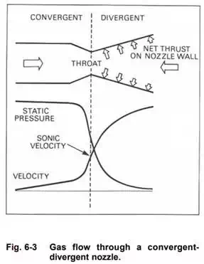
From the illustration (fig. 6-3), it will be seen that the convergent section exit now becomes the throat, with the exit proper now being at the end of the flared divergent section. When the gas enters the convergent section of the nozzle, the gas velocity increases with a corresponding fall in static pressure. The gas velocity at the throat corresponds to the local sonic velocity. As the gas leaves the restriction of the throat and flows into the divergent section, it progressively increases in velocity towards the exit. The reaction to this further increase in momentum is a pressure force acting on the inner wall of the nozzle. A component of this force acting parallel to the longitudinal axis of the nozzle produces the further increase in thrust.
The propelling nozzle size is extremely important and must be designed to obtain the correct balance of pressure, temperature and thrust. With a small nozzle these values increase, but there is a possibility of the engine surging (Part 3), whereas with a large nozzle the values obtained are too low,
A fixed area propelling nozzle is only efficient over a narrow range of engine operating conditions. To increase this range, a variable area nozzle may be used. This type of nozzle is usually automatically controlled and is designed to maintain the correct balance of pressure and temperature at all operating conditions. In practice, this system is seldom used as the performance gain is offset by the increase in weight. However, with afterburning a variable area nozzle is necessary and is described in Part 16.
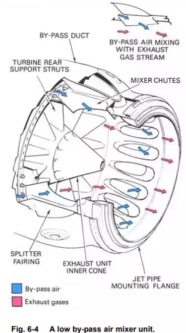
The by-pass engine has two gas streams to eject to atmosphere, the cool by-pass airflow and the hot turbine discharge gases.
In a low by-pass ratio engine, the two flows are combined by a mixer unit (fig. 6-4) which allows the by-pass air to flow into the turbine exhaust gas flow in a manner that ensures thorough mixing of the two streams.
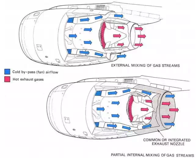
In high by-pass ratio engines, the two streams are usually exhausted separately. The hot and cold nozzles are co-axial and the area of each nozzle is designed to obtain maximum efficiency. However, an improvement can be made by combining the two gas flows within a common, or integrated, nozzle assembly. This partially mixes the gas flows prior to ejection to atmosphere. An example of both types of high by-pass exhaust system is shown in fig, 6-5.
Construction and Materials
The exhaust system must be capable of withstanding the high gas temperatures and is therefore manufactured from nickel or titanium. It is also necessary to prevent any heat being transferred to the surrounding aircraft structure. This is achieved by passing ventilating air around the jet pipe, or by lagging the section of the exhaust system with an insulating blanket (fig. 6-6). Each blanket has an inner layer of fibrous insulating material contained by
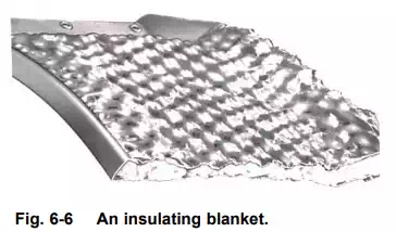
an outer skin of thin stainless steel, which is dimpled to increase its strength. In addition, acoustically absorbent materials are sometimes applied to the exhaust system to reduce engine noise.
When the gas temperature is very high (for example, when afterburning is employed), the complete jet pipe is usually of double-wall construction with an annular space between the two walls. The hot gases leaving the propelling nozzle induce, by ejector action, a flow of air through the annular space of the engine nacelle. This flow of air cools the inner wall of the jet pipe and acts as an insulating blanket by reducing the transfer of heat from the inner to the outer wall.
The cone and streamline fairings in the exhaust unit are subjected to the pressure of the exhaust gases; therefore, to prevent any distortion, vent holes are provided to obtain a pressure balance.
The mixer unit used in low by-pass ratio engines consists of a number of chutes through which the bypass air flows into the exhaust gases. A bonded honeycomb structure is used for the integrated nozzle assembly of high by-pass ratio engines to give lightweight strength to this large component.
Due to the wide variations of temperature to which the exhaust system is subjected, it must be mounted and have its sections joined together in such a manner as to allow for expansion and contraction without distortion or damage.