Centrifugal Compressor
Centrifugal compressors are often used in small turbines both in aircraft and
industrial uses. One reason is that, compared to axial flow compressors, they
offer higher pressure ratios per stage. Centrifugal compressors also provide a
wider range of operation, offering better off-design performance. The drawback
is lower isentropic efficiencies than axial compressors, with higher fluid
losses. And a larger frontal area, which can be undesirable for aircraft
application. Since the same pressure rise can be accomplished with fewer stages
centrifugal compressors are the choice for compact units and the larger
operational span make them appropriate for applications where adjustable output
and robustness is priority.
The main parts of the centrifugal compressor are the rotor and stator, often called impeller and diffuser respectively. Fluid flows axially into the center of the impeller and is then turned radial and flung outwards, kinetic energy being imparted to the flow. In the diffuser the cross sectional area of the flow is increased, decreasing the velocity and increasing pressure. The compressor used for this project is the centrifugal compressor.
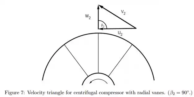
Centrifugal compressors can be divided into three categories depending on the angle of the vanes at the outlet: forward curved, β2 > 90◦ , radial, β2 = 90◦ and backward curved, β2 < 90◦ . As can be seen from figure [3] the tangential component of V2 varies with β2 in such a way that with forward curved blades it is greater, and with backwards curved it is lesser. That means that for forward curved vanes the energy transfer is larger, but at the price of larger fluid losses. And respectively backwards curved vanes trade smaller losses, and higher efficiency, with a lower energy transfer. Radial vanes are a compromise between the too and have the added benefit of being easier to manufacture, with simpler geometry and no bending stresses to take in to account.