Compressors and Turbines
There are mainly two types of compressors and turbines used in jet engines and power turbines: axial and radial/centrifugal. Both are of the continuous flow variety, where a rotating mechanical part exchanges energy on a continuous flow of air. Both are composed of two main parts, a rotating and a static part. The rotating part, rotor, transfers kinetic energy to/from the fluid. In the the static part, stator, the kinetic energy is converted to pressure by redirecting the flow and by increasing the flow area to slow the fluid down. Or vice versa, to convert pressure to kinetic energy. Each pair of rotor and stator is called a stage and are compounded in order to achieve greater pressure differentials. In axial compressors, the pressure rise per stage is usually in the range 1.1:1 to 1.4:1, whereas centrifugal regularly operate around 3:1 and in extreme cases up to 12:1. The stages are usually compounded and some designs use a mixture of radial and axial. In high performance applications, such as in modern aircraft engines, many stages are used to achieve total pressure ratios of up to 40:1 . For turbines the axial type is almost exclusively used as the pressure differential needed is lower, and isentropic efficiency is more important.
Performance prediction for compressors and turbines
Using a model of simple one dimensional flow, a way to describe the gas stream is to use three basic equations. These are derived from conservation of mass, conservation of momentum and conservation of energy.
The mass of the gas is conserved, with the fluid seen as a continuum this can be formulated as:
![]()
where
m˙ is the mass flow rate of the fluid
ρ is the fluid density
A is the cross sectional area of the passage
V is the velocity of the fluid
This can be written in differential form
![]()
known as the continuity equation.
Conservation of momentum, or more specifically conservation of angular momentum can be formulated in what’s known as Euler’s turbine equation, or the momentum equation. The change in angular momentum on the fluid stream passing over the rotor is equal to the torque from the rotor. This can be written as:
![]()
the product of the torque and the angular velocity is the rate of energy transfer
![]()
so the specific work, eW , can be written as
![]()
where U1 and U2 is the tangential velocity of the rotor, blade velocity, at respective radii. Note the sign, by convention work done by the fluid is defined as positive, so for a compressor this expression would be negative.
In the case of an axial rotor, the blade velocity is constant from inlet to outlet, U1 = U2, so
![]()
And for the case of a centrifugal compressor with no pre-whirl, the incoming flow has no tangential component, vθ,1 = 0, so
![]()
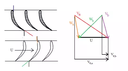
Figure 6: Velocity triangles for axial turbine. W is the relative stream velocity