Rotors & Stators
Rotors
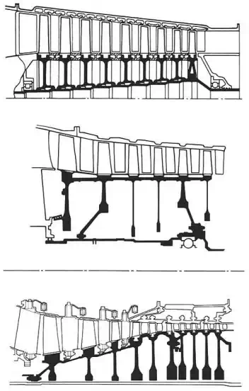
In compressor designs (fig. 3-10) the rotational speed is such that a disc is required to support the centrifugal blade load. Where a number of discs are fitted onto one shaft they may be coupled and secured together by a mechanical fixing but generally the discs are assembled and welded together, close to their periphery, thus forming an integral drum.
Typical methods of securing rotor blades to the disc are shown in fig. 3-11, fixing may be circumferential or axial to suit special requirements of the stage. In general the aim is to design a securing feature that imparts the lightest possible load on the supporting disc thus minimizing disc weight. Whilst most compressor designs have separate blades for manufacturing and maintainability requirements, it becomes more difficult on the smallest engines to design a practical fixing. However this may be overcome by producing blades integral with the disc; the so called 'blisk'.
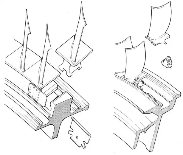
Fig. 3-11 Methods of securing blades to disc
Rotor blades
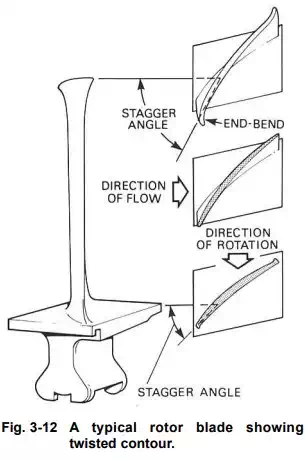
The rotor blades are of airfoil section (fig. 3-12) and usually designed to give a pressure gradient along their length to ensure that the air maintains a reasonably uniform axial velocity. The higher pressure towards the tip balances out the centrifugal action of the rotor on the airstream. To obtain these conditions, it is necessary to 'twist' the blade from root to tip to give the correct angle of incidence at each point. Air flowing through a compressor creates two boundary layers of slow to stagnant air on the inner and outer walls. In order to compensate for the slow air in the boundary layer a localized increase in blade camber both at the blade tip and root has been introduced. The blade extremities appear as if formed by bending over each corner, hence the term 'end-bend'.
Stator vanes
The stator vanes are again of airfoil section and are secured into the compressor casing or into stator vane retaining rings, which are themselves secured to the casing (fig. 3-13). The vanes are often assembled in segments in the front stages and may be shrouded at their inner ends to minimize the vibrational effect of flow variations on the longer vanes. It is also necessary to lock the stator vanes in such a manner that they will not rotate around the casing