Reaction engines
In order to provide thrust all aircraft engines work by imparting rearward momentum to one or more streams of gas, this gas is the reaction mass and such engines are known collectively as reaction engines. From Newtons laws of motion we know that force is equal to change in momentum, so net thrust, Fn for a jet engine can be written as follows, know as the general thrust equation
![]()
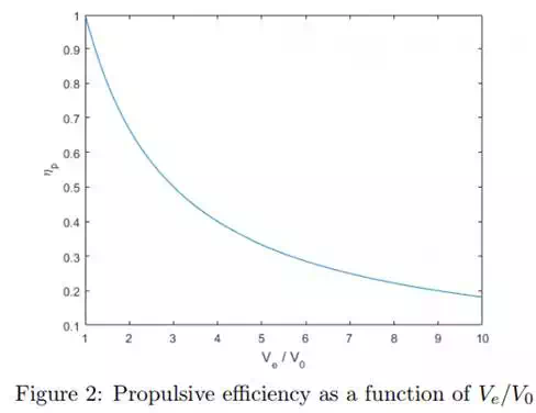
Since ˙mair >> m˙ fuel we can make the simplification that the mass flow rate entering the engine is the same as the mass flow rate exiting the engine, and from there we get a simple expression for the propulsive efficiency, ηp, which is the ratio between the work done on the aircraft compared to the kinetic energy imparted to the air stream flowing through the engine:
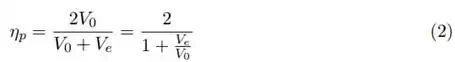
From this the conclusion can be made that the highest efficiency is achieved when the velocity of the exhaust is nearly the same as that of the aircraft, shown in fig. 2. Using a larger mass flow rate instead of higher exhaust velocities is there for preferable. Depending on the range of speeds an aircraft is designed to operate in the preferred engine type varies, with slow aircraft the choice is propellers, followed by high-bypass turbofan and then progressively lower bypass ratios as the speed increases.
Cycle Overview
The turbojet engine is a heat engine, which works by converting heat to useful mechanical work. In this case, the heat from combustion is used to propel the air rearwards. With the help of a thermodynamic cycle an ideal case of the jet engine’s operation can be shown. This is a good way to calculate the overall efficiency of the engine.
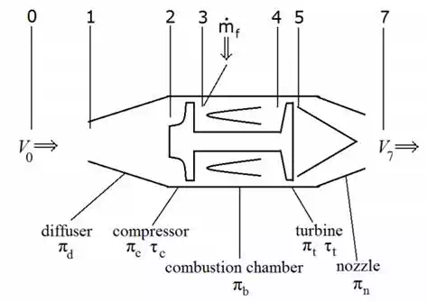
Figure 3: A schematic view of a turbojet
The turbojet engine consists of five main regions. Diffuser, compressor, combustion chamber, turbine and nozzle. There are also numbered station which are used for describing the state of the flow at different points in the engine. A schematic view is shown in figure 3. The zeroth station is far enough up stream before the intake that ambient conditions apply. The region between stage one and two is the diffuser, where the stream is slowed down, and the pressure rises. The region between 2 and 3 is the compressor, where energy is added to the flow, idealized as an adiabatic process where the pressure and the temperature increases and the volume decreases. Between station 3 and 4 the combustion takes place, heat is added and the volume and the entropy increases and the temperature reaches its peak. Between station 4 and 5 is the turbine, where the pressure and the temperature decreases and the volume increases while the air flows through the turbine, converting heat to mechanical work. Finally, between 5 and 6, the air goes through a nozzle back to ambient pressure, while accelerating.
To describe the flow and thermodynamic properties a number of approximations and idealizations are made. We assume frictionless and inviscous flow to avoid fluid losses. We use the equation of state for ideal gas: p/ρ = RT. These equations offer results that can be used for a qualitative overview and preliminary design decisions.
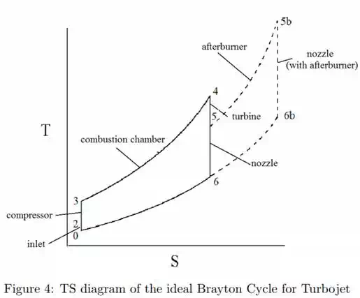
The ideal open Brayton cycle consists of 4 processes, isentropic compression, isobaric heat addition and isentropic expansion and then an isobaric heat rejection between exit and inlet. We can see these relationships:
Work done by compressor:
![]()
Work done on turbine:
![]()
Heat added to system during combustion:
![]()
Heat rejected from the system in the gas stream:
![]()
The work done by the gas on the turbine is in a turbo jet only used to drive the compressor and various auxiliaries. The energy left in the gas stream after the turbine and how that is converted to propulsive force is what is of interest in this context.
Using conservation of energy, assuming that the change in potential energy due to elevation is negligible and assuming conservation of mass (neglecting fuel flow since m˙ air >> m˙ fuel)
![]()
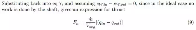
Using the thrust equation from the previous section, eq 1, the kinetic energy term can be written as
![]()
Define the over all efficiency of the engine, the ratio of work done by the exiting stream to the rate of heat added
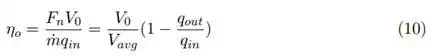
Propulsive efficiency, eq 2 can be rewritten as ηp = V0/Vavg, thus overall efficiency can be stated as a product of propulsive and thermal efficiency, ηo = ηpηth, where thermal efficiency is defined as
![]()
Both heat in and heat out are constant pressure processes, approximating constant specific heat Cp = Cp,avg, equation 11 become
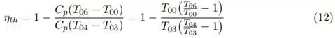
Compression and expansion is assumed to be isentropic and we assume polytropic gas. And P03 = P04 and P06 = P00 so
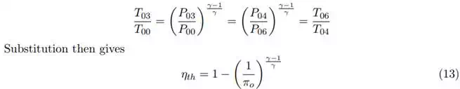
where πo = P03/P00 = P04/P06 is the overall pressure ratio of the engine. As fuel efficiency is directly related to thermal efficiency, as high a pressure ratio, and temperature ratio as possible is desired.

In the actual cycle there are a number of differences with regard to the ideal case. Compression and expansion is not isentropic, and there are pressure losses along the whole path that the air takes in the engine. The isentropic efficiency for the compressor and turbine is an expression for the differences between the ideal case and the actual case, a meassure of how much of the theoretically available heat that is converted to work on the rotor in the case of the turbine, and for compressors how much of the mechanial work done by the rotor leads to increase in energy of the gas.