Aerodynamic measurements
Limitations of magnetic balances
The disadvantages of magnetic balances have so far limited the spread of their use to industrial wind tunnels: the first is the high investment and management costs due to maintenance and to the high consumption of electricity and of cryogenic liquids.
In addition to this economic aspect, the use of magnetic balances can also lead to some technical and operational problems such as:
■ interference from high intensity magnetic fields on control and measurement systems as pressure transducers housed in the model;
■ the risk of damage to both the model and wind tunnel due to the possible loss of control of the model;
■ the difficulty of performing certain experiments as, for example, simulation of propulsion. This type of testing requires the use of gas to be expelled from the model to simulate the presence of a jet. In a conventional wind tunnel, gas is supplied to the model through the support, in a magnetic suspension system, the gas must be contained in tanks housed within the model with space problems;
■ the difficulty of flow visualization (Schlieren, interferometry, etc.) both for the poor optical access to the model and for the possible interference with the optical control systems.
For all these reasons, to date, magnetic balances have been used only in
Determination of forces and moments
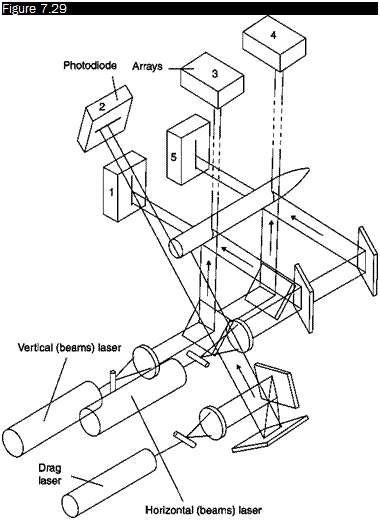
The number of degrees of freedom of the system depends on both the number and location of the electromagnets and the number of households accommodated within the model. The system in Figure 7.29 can control, for example, only five degrees of freedom (the three shifts and two rotation axes of pitch and yaw) because there is only one core whose magnetization vector is characterized by a single component along the longitudinal axis of the model.
In the case of a model aircraft, the rolling moment is obtained with magnetic cores put in the wings, or building the wings with magnetic material.
|
|
Arrangement of position sensors in a five-component balance
Position and attitude sensors
Model position detection system can be formed by optical sensors and helium-neon lasers outside the test chamber. The sensors are a combination of linear photodiodes. A typical sensor consists of 1024 photodiodes and has a linear dimension of 1 in., the precision of position detection is therefore about 25 mm. Laser beams, to illuminate the sets of linear photodiodes, are made plane through cylindrical lenses. The position and attitude of the model are obtained by the shadow of the model on the sensors and are measured by the number of illuminated photodiodes. Models are usually painted in matt black in order to avoid possible light reflections.
The number and location of optical sensors and lasers are functions of the number of degrees of freedom to be controlled. Figure 7.29 illustrates the schema of a system of position and attitude sensors in a balance with five degrees of freedom; lacking the sensitivity to roll, only tests on axially symmetric bodies are allowed. The longitudinal position is detected by sensor 2 through the partial shielding of the drag laser beam; the vertical position and the pitch angle from sensors 1 and 5 through the partial shielding of the horizontal laser beams, and finally the transverse position and the yaw angle by sensors 7 and 4 through the partial shielding of the vertical laser beams. Other detection systems may be an X-ray system or a television system.
Electromagnets
Electromagnets consist of coils, usually copper, wrapped tightly around a laminated core of ferromagnetic material (soft iron, steel, cobalt). Electromagnets require a refrigeration system, generally water, to dispose of heat produced by the dissipated electricity.
Each plant is characterized by its pattern of electromagnets around the test chamber and by their constructive solutions. The schema of a quite complex plant built at the Southampton University is shown in Figure 7.28: ten magnets, disposed in antagonistic pairs, ensure the
|
|
Positions of magnets in a six-component balance at Southampton University, UK
symmetry along the three axes of the wind tunnel, then the system is able to control all degrees of freedom of the model. Magnets 1, 3, 5, 7 control vertical position and pitch angle, magnets 2, 4, 6, 8 control transverse position and yaw angle, while magnets 9 and 10 control the longitudinal position. The roll angle is controlled by the electromagnets from 1 to 8.