Introduction to Aerodynamics
Flying... still kind
of magic every time. The math describing Fluid Dynamics was extensively studied
and eventually written down in a complete set of Partial Differential Equations
known as the Navier-Stokes. Those
equations are so involved that mathematicians had been working on them for
years trying to find out some assumption that could lead to a simplified
sub-set, detailed enough to study basic aerodynamics in closed form. One of the
most abused assumption was to discard the friction from the equation (potential
flow only). That
looked to be a reasonable assumption (as friction in the air is low compared to
other factors), however it leads to the impossible result that no drag exists and thus nothing
can fly! (known as the D'Alambert paradox).
It was only in early 1900 that two brothers figured it out,
and it's been an evolution ever since.
It is all a matter of Friction.....
Without
friction, the air particles would not stick to any surface and would not create
the well-known boundary layer, responsible
for the Lift force we all know.

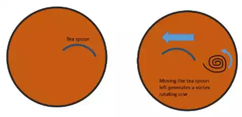
Want
to visualize the Boundary Layer? Try the following experiment: during your
coffee break, take a spoon and dip it half into the liquid. Then suddenly move
it right or left: you will notice a vortex separating from the spoon's trailing
edge. That vortex is equal to the sum of all the inverse-rotating tiny vortices
on the spoon surface, generated by the boundary layer. As soon as you stop the
spoon, a new vortex on the other side will separate, spinning in the opposite
direction: the total vorticity remains constant and that is the key to fly
(have you noticed that the tea-spoon section resemble a thin wing airfoil?)
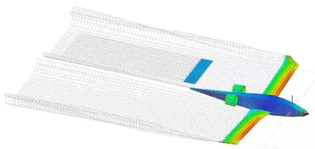
The
super-complex complete Navier-Stokes set can be
then separated
in two regions: the Baundary Layer, where
all the vorticity is assumed to be confined, and the outer layers, assumed to
be a inviscid potential flow. This
assumption actually works pretty well and has been applied in all Vortex
Lattice Method based softwares commonly
used by R/C air model designer (try the MIT's AVL!)
Airfoils: Lift and Drag
So
what makes something fly? Let's find out. For sake of
simplicity we will refer to a 2D example, so we consider an airfoil as a section of an infinite long wing. What I
am going to illustrate is valid in subsonic regime, while most of the concept
can be applied even in supersonic (but wired things happen in
transonic-supersonic flight... not a matter of my posts).
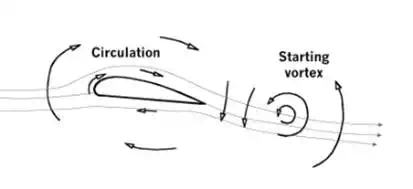
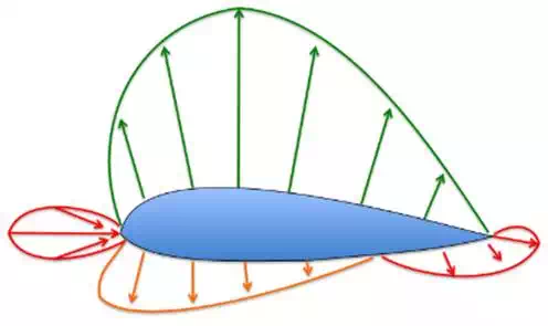
Essentially
the flow around an airfoil separates at the
nose and joins again at the trailing edge: the vorticity causes the fluid to
change its velocity (direction and magnitude), thus resulting in a net force on
the body (action/reaction). The pressure distribution along the airfoil contour shows a strong suction on
the upper side, that eventually integrated all over the profile leads to
the Lift Force (sum of all the forces normal to the air
stream). The Drag force instead is the sum of all the forces along the the main stream, both due to friction and pressure.
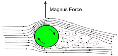
The
rotation is what makes the fluid change its velocity, and that is much more clear if we consider a spinning football.
The
Lift Force can be expressed in terms of a non
dimensional value, named Lift Coefficient (CL) as:
Lift (L) = q*S*CL
where q = 0.5 *rho*V^2 is the Dynamic
Pressure, given by
the product of the air density (rho) times the air velocity squared (V). S is
a reference surface (in 3D), or a reference length (in
2D).
The
CL happens to be linear with the angle of attack up to a value known as Stall, at which the boundary layer begins to
separates from the airfoil. Increasing the angle
of attack beyond the stall leads to a small increase of the CL up to the CL_Max, but suddenly it drops, together with a strong
increase of total Drag.
So
we can approximately say: CL = CL_0 + CL_alpha * alpha, being CL_0
the zero incidence lift coefficient and CL_alpha the
slope coefficient (that usually has an order of magnitude of 0.1 per degree)
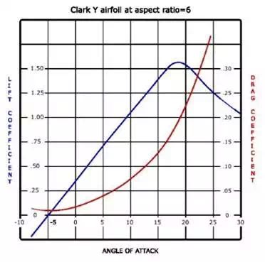
Same
theory and observations lead to describe the Drag Force as a
function of a Drag Coefficient CD, which is function of CL^2 as:
CD = CD0 + k*CL^2
Where
CD0 is due to the friction and k is a proportional coefficient (it reduces as
the span to chord ratio of a wing increases).
As
you can see, given a certain Surface S and a flight velocity V (and from the
altitude we calculate q) and knowing the aircraft's weight W, it is easy to
evaluate the CL needed to fly and the correspondent angle of attack as:
CL_flight = W/(q*S)
--> alpha_flight = CL_flight / CL_alpha
CD_flight = CD0 + k*CL_flight^2
There
exists an angle of attack at which the airplane will flight at
maximum efficiency, and that is the angle where the ratio CL/CD is maximum.
> Want to
play around with airfoils? Try NASA's Foilsim software
Airfoil camber...
Why?
The
highest theoretic lift coefficient is achieved by a flat panel.... And you
could wonder why are wings not as straight?
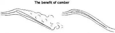
Well, theory does not work always so well, and in particular what the
simplified Lifting Theory I've been mentioning can't describe is the fluid
separation from the wing surface. At the stall point the boundary layer becomes
so thick and slow that eventually start separating from the wing, creating
vortices and dropping the lift force to almost zero. In order to increase the
stall angle of attack the camber comes to help out.
Warbirds or jet fighter wings....
We
discovered that the Lift force has multiple factors:
● Speed^2
(the faster you go, the more is the lift)
● Surface
(the bigger is the wing the more is the lift)
● Airfoil Camber (the more curved the airfoil, the the more
is the lift at zero angle of attack)
● Angle of
Attack (the more you tilt your nose up the higher is the lift)
What
does it mean? Well, if your aircraft is heavy and slow you would probably
considering a huge wing and a cambered profile, while for a jet plane you want
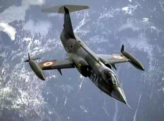
to reduce the wing surface and using thinner profiles. That may explain why the
early aircrafts needed such a huge surface in order to fly, so big that they
eventually ended up splitting it in 2 or three wings (biplane or tri-plane). As
the motors power increased, the wings shrank to the dimensions of the tiny
F-104's one...
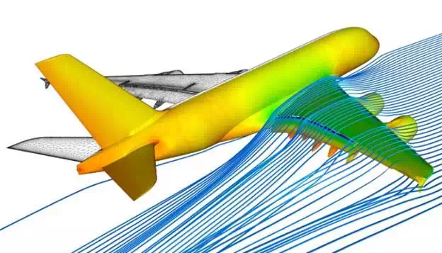
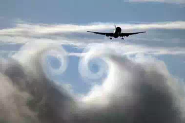
Wing Tip Vortex: where most of the Drag comes from...
Have
you ever seen a picture like that? Cool, isn't it? Well it is not a fake nor
a photoshop effect, it is real and that is
a visualization of what happen to be the major contribution to aerodynamic Drag.
Remember
that I showed you a low pressure on the upper side of the airfoil? Well, for a wing is not infinite and a fluid goes
from high to low pressure regions, the lower fluid finds its way around the
wing tip in order to reach the low pressure region on the top side.
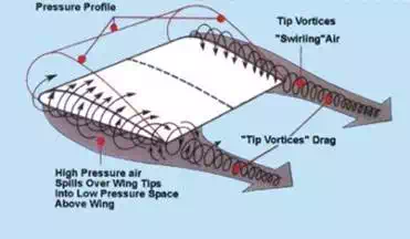
Now
you can easily realize why most modern aircraft use to have winglets at the
wing tip: that in order to reduce the tip vortex and to save lots of money in
jet fuels...
WHAT HAVE WE DISCOVERED?
Impossible
to write any longer. Next time we are going to explain some basics concept
about propellers and rotors. Next steps then will be airplane and multirotor
flight mechanics. We will quickly give some short hints about helicopter dynamics, that being quite a complex matter.
In
this post we've learnt:
● Where does
the lift come from (low pressure region over the wing)
● How to
mathematically represent a fluid in order to have quick yet reliable results
(vortex lattice methods)
● How Lift
and Drag vary with the angle of attack
● Where the
majority of the aerodynamic Drag comes from
REFERENCES:
Navier-Stokes equations, Potential Flow, D'Alambert Paradox, Lift Coefficient, Airfoil Aerodynamics, Lift by turning, Wing Vortices, Vortex Lattice Method