Intake Performance
The intakes of the vehicle (i.e. aircraft, cruise missile etc) deliver the air to the engines. It is important that the air flowing into any engine is well behaved so that the engines operate efficiently and reliably with minimal maintenance. The intakes must retain optimal functionality throughout the operational envelope whatever the speed or attitude of the vehicle.
ARA has extensive experience in the design and manufacture of bespoke ejectors and engine face rakes together with appropriate intake models and support structures. We also have an on-site intake/duct calibration facility: the Mach Simulation Tank. It can be used to calibrate model engine nacelle/duct/intake thrust and discharge coefficients over the range of pressure ratios experienced in both the Transonic Wind Tunnel and a quiescent environment. This facility may also be used to check the operation of engine face rakes.
Due to the dynamic nature of air flow, a high speed data acquisition system is also vital. ARA has a bespoke system for the acquisition of high speed steady state and dynamic data in real time during testing. Coupled with real time data reduction techniques this system provides immediate access to the results of pressure recovery and distortion using the ARA data monitoring system.
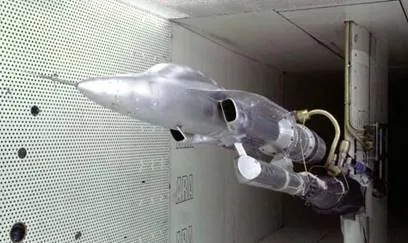
An intake test involves the design and manufacture of a model of an appropriate section of the vehicle to be tested (for an aircraft this might be the forward fuselage only, whilst for a missile it may consist of most of the fuselage and the wings in the appropriate deployed position). Integrated into this model is an ejector – powered by a supply of high pressure air – which induces the required air flow through the intake. An array of measurement probes, usually in the form of an engine face rake, is used to record the pressures of the airflow as it approaches the position of the engine. Temperatures are also commonly recorded.
Tests are usually undertaken over a range of Mach numbers, mass flows, model attitudes and configurations to provide sufficient information for the determination of total pressure recovery and distortion at the engine face and evaluate an intake or engine compatibility envelope over an appropriate full flight spectrum. The effects of mass flow restrictors positioned within the inlet can also be investigated.
Prior to testing in the wind tunnel it may be necessary to calibrate the mass flow control system being used. These calibrations are performed in the ARA Mach Simulation Tank.