Wind tunnel measurements
pressure distribution
This is used for studying pressure distribution across various models such as Airfoil, cylinder, special purpose shapes . It contains 13 Nos. Of tubes mounted on board with adjustable inclination. Bottom of all tubes are interconnected and in turn to the balancing reservoir filled with coloured water . While the last tube is left open to atmosphere for reference , all other 12 tubes are connected at their top to pipe / tube bundles of the model. The required model is held in the test section between holes provided front and back side Perspex windows. The pressure tapings ( tube outlets ) are connected to the glass limbs of the respective Serial Number . The required degree of angle of inclination can be given to the tube bundle and angle measured with respect to the horizontal .
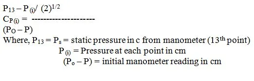
The coefficient of pressure is obtained by
velocity measurement. Pitot probe
One very important use of wind tunnels is to visualize flow patterns and measure the pressure at a selected point in the flow field and compute the corresponding speed of air. The equation relates the speed of the fluid at a point to both the mass density of the fluid and the pressures at the same point in the flow field. For steady flow of an incompressible fluid for which viscosity can be neglected, the fundamental equation has the form
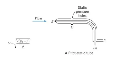
Where V is the speed of the fluid, P0 is the total, also called the stagnation, pressure at that point of measurement, and p is the static pressure at the same point. This equation comes from the application of Bernoulli’s equation for the steady flow of an incompressible and inviscid fluid along a streamline. Bernoulli’s equation is typically obtained by integrating Euler’s equations along a streamline. It will be recalled that Euler’s equations are a special case of the Navier -Stokes equations, when the viscosity of the fluid has been neglected. The Navier-Stokes equations, in turn, are obtained from Newton’s second law when it is applied to a fluid for which the shear deformation follows Newton’s law of viscosity
force coefficients from pressure distribution
By integration the surface pressure coefficient distribution, one can obtain the lift, pressure drag, and pitchining moment coefficients. The lift force is the force acting on the airfoil section perpendicular to the mean flow direction. The pitch moment is the moment about the quarter chord point, positive when nose up. We measure aerodynamic quantities in the middle of the airfoil section and assume that the flow is approximately two-dimensional. In this special case it is convenient to look at the force and moment per unit span. The section lift, pressure drag and moment coefficients are respectively defined as
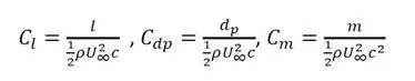
With L the lift force per unit span, dp the drag force per unit span and m the pitch moment per unit span and c is the chord length.
forces from strain gauge load cells
a) WIND TUNNEL BALANCE :
The tunnel balance is three component type ( three forces ) designed using the electrical strain gauges to indicate separately on the digital indicator. The balance is intended for indicating the lift , drag & side force in case of airfoils, and drag force only in case of bluff bodies,Viz., spherical, Hemi - spherical, Flat disc. These models are mounted on the string (Vertical square rod) situated exactly beneath the test section. The output from the lift, drag & side forces (strain gauges) are connected to the respective multi - pin sockets provided at control panel.
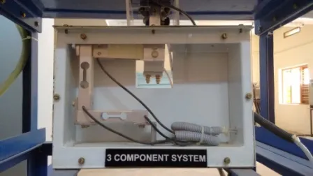
View of the Load cell balance (Wind tunnel) at Amrita Virtual Lab