Physical parameters
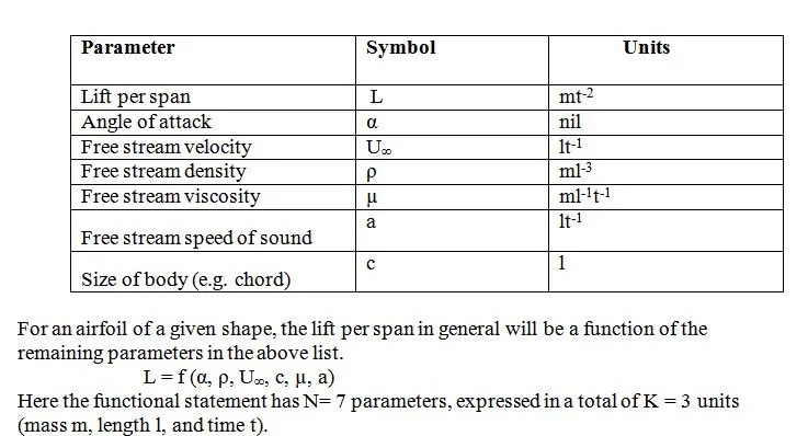
A large number of physical parameters determine aerodynamic forces and moments. Specifically, the following parameters are involved in the production of lift.
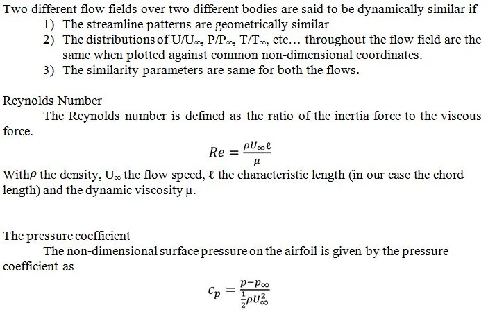
The distribution of the pressure coefficient integrated along the airfoil section contour yields the lift and moment coefficient.
By integration the surface pressure coefficient distribution, one can obtain the lift, pressure drag, and pitching moment coefficients. The lift force is the force acting on the airfoil section perpendicular to the mean flow direction. The pitch moment is the moment about the quarter chord point, positive when nose up. We measure aerodynamic quantities in the middle of the airfoil section and assume that the flow is approximately two-dimensional. In this special case it is convenient to look at the force and moment per unit span.
The choices for S and Lare arbitrary, and depend on the type of body involved. For aircraft, traditional choices are the wing area for S, and the wing chord or wing span for ℓ and the dynamic pressure for q∞ .The non-dimensional lift, pressure drag and moment coefficients are respectively defined as :
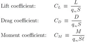
With L the lift force per unit span, D the drag force per unit span and M the pitch moment per unit span.
The lift coefficient
The lift coefficient is a number that aerodynamicists use to model all of the complex dependencies of shape, inclination, and some flow conditions on lift. The lift coefficient expresses the ratio of the lift force to the force produced by the dynamic pressure (q∞) times the area. By knowing the lift coefficient, we can predict the lift that will be produced under a different set of velocity, density (altitude), and area conditions using the lift equation. For given air conditions, shape, and inclination of the object, we have to determine a value for CL to determine the lift.
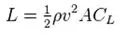
Where L is the lift force, ρ is air density, Ʋ is the true air speed, A is the planform area (projected area of the wing) and CL is the lift coefficient.
The Drag coefficient
The drag coefficient is a number used to model all of the complex dependencies of shape, inclination, and flow conditions on aircraft drag. The drag coefficient expresses the ratio of the drag force to the force produced by the dynamic pressure times the area. In a controlled environment (wind tunnel) we can set the velocity, density, and area and measure the drag produced. Through division we arrive at a value for the drag coefficient. As pointed out on the drag equation slide, the choice of reference area (wing area) will affect the actual numerical value of the drag coefficient that is calculated. We can predict the drag that will be produced under a different set of velocity, density (altitude), and area conditions using the drag equation.
For given air conditions, shape, and inclination of the object, we must determine a value for CD to determine drag. Determining the value of the drag coefficient is more difficult than determining the lift coefficient because of the multiple sources of drag. The drag coefficient given above includes form drag, skin friction drag, wave drag, and induced drag components.
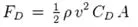
Where FD is the drag force, is the mass density of the fluid, is the velocity of the object relative to the fluid, A is the reference area, and CD is the drag coefficient.
For 2-D bodies such as airfoils, the appropriate reference area/span is simply the chord c, and the reference length is the chord as well. The local coefficients are then defined as follows.

These local coefficients are defined for each span wise location on a wing, and may vary acrossthe span. In contrast, the CL, CD, CM are single numbers which apply to the whole wing.