Block Diagrams
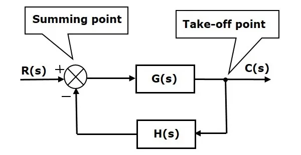
The basic elements of a block diagram are a block, the summing point and the take-off point. Let us consider the block diagram of a closed loop control system as shown in the following figure to identify these elements.
The above block diagram consists of two blocks having transfer functions G(s) and H(s). It is also having one summing point and one take-off point. Arrows indicate the direction of the flow of signals. Let us now discuss these elements one by one.
The transfer function of a component is represented by a block. Block has single input and single output.
The following figure shows a block having input X(s), output Y(s) and the transfer function G(s).

Transfer Function,G(s)=Y(s)X(s)G(s)=Y(s)X(s)
⇒Y(s)=G(s)X(s)⇒Y(s)=G(s)X(s)
Output of the block is obtained by multiplying transfer function of the block with input.
The summing point is represented with a circle having cross (X) inside it. It has two or more inputs and single output. It produces the algebraic sum of the inputs. It also performs the summation or subtraction or combination of summation and subtraction of the inputs based on the polarity of the inputs. Let us see these three operations one by one.
The following figure shows the summing point with two inputs (A, B) and one output (Y). Here, the inputs A and B have a positive sign. So, the summing point produces the output, Y as sum of A and B.
i.e.,Y = A + B.

The following figure shows the summing point with two inputs (A, B) and one output (Y). Here, the inputs A and B are having opposite signs, i.e., A is having positive sign and B is having negative sign. So, the summing point produces the output Y as the difference of A and B.
Y = A + (-B) = A - B.

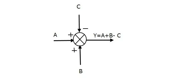
The following figure shows the summing point with three inputs (A, B, C) and one output (Y). Here, the inputs A and B are having positive signs and C is having a negative sign. So, the summing point produces the output Y as
Y = A + B + (−C) = A + B − C.
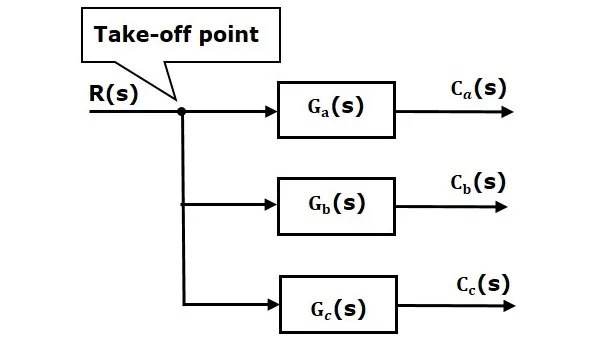
The take-off point is a point from which the same input signal can be passed through more than one branch. That means with the help of take-off point, we can apply the same input to one or more blocks, summing points.
In the following figure, the take-off point is used to connect the same input, R(s) to two more blocks.
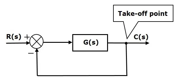
In the following figure, the take-off point is used to connect the output C(s), as one of the inputs to the summing point.
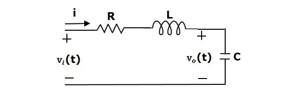
In this section, let us represent an electrical system with a block diagram. Electrical systems contain mainly three basic elements — resistor, inductor and capacitor.
Consider a series of RLC circuit as shown in the following figure. Where, Vi(t) and Vo(t) are the input and output voltages. Let i(t) be the current passing through the circuit. This circuit is in time domain.
By applying the Laplace transform to this circuit, will get the circuit in s-domain. The circuit is as shown in the following figure.
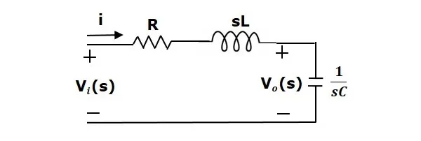
From the above circuit, we can write