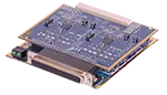
UEI’s DNx-1553-553 MIL-STD-1553 I/O board features 2 Independent and dual redundant bus interfaces, BC/RT/MT modes, Multiple RT simulation up to 32 RTs, Supports 1553A or 1553B protocols (including notice 2), and Transformer or Direct Coupling.
THE PHYSICAL MIL-STD-1553 IO BOARD
A single 1553 bus consists of a shielded twisted-wire pair with 70 - 85 ohm impedance at 1 MHz. If a coaxial connector is used, the center pin is used for the high Manchester bi-phase signal. All transmitter and receiver devices connect to the bus either through coupling transformers or directly through stub connectors and isolation transformers, as shown below. Stubs can be a maximum of 1 foot in length for direct coupling or a maximum of 20 feet for transformer coupling. To limit reflections, the data bus must be terminated by resistors equal to the cable characteristic impedance (within ±2%). The below image shows one of the two buses. Each transceiver is also connected in the same way to the second (redundant) bus. Our 1553 IO board has 2 channels. Each channel is an independent 1553 System that supports Bus A and Bus B.
| UEI’s DNx-1553-553 MIL-STD-1553 I/O board features 2 Independent and dual redundant bus interfaces, BC/RT/MT modes, Multiple RT simulation up to 32 RTs, Supports 1553A or 1553B protocols (including notice 2), and Transformer or Direct Coupling. |
BUS PROTOCOL
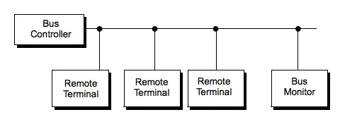
All 1553 messages on the bus contain one or more 16-bit words, classified as command, data, or status word types. Each word is preceded by a 3 ms sync pulse and is followed by an odd parity bit. Note that since the sync pulse — 1.5 ms low followed by 1.5 ms high — cannot occur in a Manchester code, it is therefore unique. The words in a message are transmitted with no gap between words, but a 4 ms gap is inserted between successive messages. All devices must start transmitting a response to a command within 4 to 12 ms. If they do not start transmitting within 14 ms, they are considered to have not received the command message.
A typical system is illustrated below.
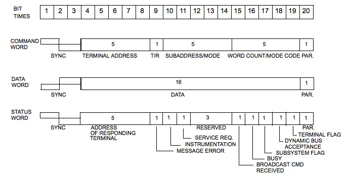
WORD FORMATS
The 1553 standard defines three word types:
· Command
· Data
· Status
Each word type has a specific format within a common structure. All words are 20 bits in length and the first three bits are a synchronization field, which enables the decoding clock to re-sync at the beginning of each new word. The next 16 bits contain the information, in a format that varies with the word type. The last bit in the word is a parity bit, which is based on odd parity for a single word.
All bit encoding is based on bi-phase Manchester II format, which provides a self-clocking waveform. The signal is symmetrical about zero and is therefore compatible with transformer coupling.
In Manchester coding, signal transitions occur only at the center of a bit time. A logic “0” is defined as a transition from negative to positive level; a logic “1” is the reverse. Note that the voltage levels on the bus are not the information signal; all information is contained in the timing and direction of the zero crossings of the signal on the bus.
The terminal hardware provides the encoding and decoding of the various word types. The encoder also calculates parity. For received messages, the decoder signals the logic what sync type a word is and whether or not parity is valid. For transmitted messages, input to the encoder defines what sync type to place at the beginning of a word. The encoder calculates parity automatically for each word.
The formats for each word type are illustrated below.