What is an inertial navigation system?
Inertial navigation systems come in all shapes and sizes. One thing they have in common though is their use of multiple inertial sensors, and some form of central processing unit to keep track of the measurements coming from those sensors. The sensors an INS uses are typically gyros and accelerometers—and there are normally several of each inside. We’ll look at how an INS actually works in a moment, for now, the most important thing to realise is how they differ from GPS—which you’re probably more familiar with.
Switch on a GPS receiver and, assuming everything works correctly, after a short time it will generate a position measurement. Ignoring the inaccuracies GPS has, the position measurement the receiver generates is quite specific. It says ‘you are at this latitude and this longitude‘—in other words, it gives us an absolute position using a known co-ordinate system. Inertial navigation systems don’t work like that. In their case, the measurement they generate is relative to their last known position. So even after an inertial navigation system has been turned on for several minutes, it can’t say ‘you are at this latitude and this longitude‘, but what it can say is, ‘you haven’t moved from where you started‘.
So why do people use inertial navigation systems at all? If they can’t tell you where you are, how were they able to navigate man to the moon, why don’t submarines crash all the time and how do aeroplanes and missiles find their way? Thankfully the answer to that question is simple. An inertial navigation system works out where it is in relation to where it started—so if you tell the INS where it started, it can easily work out where it is now, based on its own measurements. That is how spaceships, submarines, aircraft and missiles all successfully navigate using an INS—because they know where they started from.
How does an INS actually work?
An inertial navigation system comprises two-distinct parts; the first is the IMU (inertial measurement unit)—sometimes called the IRU (inertial reference unit). This is the collective name for the accelerometers and gyros that provide acceleration and angular velocity measurements. The second part is the navigation computer. The navigation computer takes measurements from the IMU and uses them to calculate the relative position, orientation and velocity of the INS.
There are essentially two kinds of navigation computers in use; stabilised platforms and strap-down navigators. Stabilised platforms use real, spinning mechanical gyroscopes to stabilise a platform that rotates independently to the INS. So, as the inertial navigation system rotates, the stabilised platform inside it does not. In this way, the system learns about its orientation and can make use of the measurements from the accelerometers. The downsides of this type of system are gimbal lock (see the section on gyros for a full explanation), the high cost and complexity.
In contrast, the sensors inside a strap-down navigator do not move independently of the INS. They are, if you like, strapped down. This overcomes many of the problems associated with stabilised platforms and is the main reason why inertial navigation systems are now affordable to a lot more people. Unlike the spinning, mechanical gyros inside a stabilised platform, the gyros used inside a strap-down navigator are typically MEMS (microelectromechanical systems), which don’t appear to have any moving parts. In fact, it’s better to think of them as angular rate sensors, rather than gyros, although that’s what they’re typically called.
So how does an INS work? In order to capture the measurements needed for navigating in 3D space, the axes of the inertial sensors are laid out in a mutually perpendicular way. In other words, each axis is at 90° to the other two (see image below).
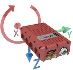
IMU frame: This image shows the three axes (xyz) that the inertial navigation system uses to measure movement and orientation. The position of the axes within the INS is fixed, so they rotate with it. Each axis measures in both directions—the arrowheads in the image show which direction is read as positive. If the INS accelerates in the direction of the green arrow, for example, the y-axis will show a positive acceleration. If the INS accelerates in the opposite direction, we would see a negative acceleration along the y-axis. Angular velocity about each axis is also measured. If the INS rotates as indicated by the circular, red arrow, we would see a positive reading on the x-axis gyro. If the INS rotates in the opposite direction we would see a negative value on the x-axis gyro.
By taking measurements along (and about) the x-, y- and z-axes, the navigation computer can understand how it is moving and rotating. In the IMU frame image, you can clearly see how the measurement xyz-axes are laid out on one of our products. You can also see a circular arrow, showing how the x-axis gyro measures angular velocity.
It’s worth pointing out that although each arrow points in one direction, the gyros and accelerometers still measure in both directions along or about each axis. The arrows simply indicate which direction the sensors see as positive movement. So if the product accelerates down (in the direction of the blue arrow), the z-axis accelerometer would indicate a positive value; if the product accelerated upwards, the z-axis accelerometer would show a negative value.
Frames of reference
At this point, we should explain what terms like IMU frame mean. A moment ago we talked about a positive measurement on the z-axis accelerometer when the product accelerates down, but what happens if we flip the INS so it’s oriented as shown in the image below? Now when the INS accelerates down, the z-axis would register a negative value. This is why frames of reference are important.

To both you and I, up means above us and down means below us. Equally, we both know which way is right and left, and if I said I moved forwards one metre, you can picture exactly what I’ve done—because you’ve put yourself into my frame of reference. As humans, we’re very good at doing that. In fact, we find it so easy to ‘see things from another point of view’ that it’s easy to forget each object has its own frame of reference, and how we describe movement depends on the frame of reference being used.
For example, picture yourself stood on a train platform. Imagine you can see someone stood inside the train carriage looking for a seat. As the train pulls out of the station the person starts to walk towards the rear of the train. From the person’s point of view, they are walking forwards at a constant speed. But to you, looking into the train from the platform’s reference frame, the person initially appears not to be moving—because they’re walking forwards (in their frame) at the same speed as the train is moving forward in its frame. As the train gets faster, however, the person will appear to move in the direction of the train’s travel. To you, they are moving backwards, but to the person on the train, they are still moving forward. Both points of view are correct, they’re just using different frames of reference.
Luckily most inertial navigation systems are smart enough to be able to convert movement from one frame of reference to another—as long as they’re given a little bit of information to begin with. So imagine holding an INS upside down, so the z-axis points up. As long as we tell the INS it’s being held upside down before we start, then when you move your hand upwards the inertial measurement unit will register a positive value on the z-axis (which points down as far as it’s concerned)—but the inertial navigation system (the computer) knows it’s actually being held upside down in your hand. So it spins all the measurements around and puts them into a different reference frame that makes sense to us; one that says the INS is moving upwards.
Accelerometers
Accelerometers are one of the sensor types used in most inertial navigation systems. As you can guess from their name, they measure acceleration, not velocity. Depending on how long it is since you had to deal with the physical properties of objects, you may recall that the SI unit of acceleration is m/s² (said: metres per second squared). A value of 1 m/s² means that for each additional second that passes, an object’s velocity will increase by an additional 1 m/s (said: metre per second).
Although an inertial navigation system doesn’t directly measure velocity, by keeping track of how much acceleration there is, and how long it lasts, the INS can easily work out what the velocity is by multiplying the acceleration by time. For example, if it saw an acceleration of 2.5 m/s² for 5 seconds, and assuming the initial velocity was 0 m/s, then the INS must now have a velocity of 12.5 m/s (2.5 m/s² × 5 s = 12.5 m/s). Distance can also be calculated. It is found using s = 0.5 × at², where s is distance, a is acceleration and t is time. In this case, assuming the inertial navigation system saw the acceleration on the x-axis, it could work out it had moved forwards 31.25 metres (0.5 × 2.5 m/s² × 5 s² = 31.25 m).
So having three accelerometers is very useful, especially when they’re arranged in a mutually perpendicular way, because they allow the INS to measure acceleration in 3D space and calculate the distance traveled as well as current velocity. However, one thing that often confuses people when they first see the data being output from a three-axis accelerometer, is why an axis pointing down shows an acceleration of -9.81 m/s²? To answer that question we need to look at how accelerometers work, and what they actually measure.
At this point, you might think, ‘hang on! Earlier you said accelerometers measure acceleration’. While it is true accelerometers do measure acceleration, we didn’t want to confuse matters by saying that what accelerometers measure is actually acceleration relative to freefall—and that’s why a vertical accelerometer at rest shows a reading of -9.81 m/s². Don’t worry if that doesn’t make sense yet, the next section explains that.
Proper acceleration
You have undoubtedly heard the name Sir Isaac Newton before and recall that he wrote some laws of motion. Newton’s first rule tells us that unless some force acts on an object, it will stay perfectly still, or carry on moving at the same speed. In other words, to get something moving, or to change its speed, we need to apply a force. His second rule describes how an object’s acceleration is related to the force acting on it, and the mass of the object. It can be summed up as force = mass × acceleration (F = ma).
Accelerometers measure acceleration relative to freefall using the principle described in Newton’s second law of motion. That is to say, they measure the relative force acting on a known mass, and use that to calculate the acceleration it must be undergoing. To understand this, let’s start by drawing a simple accelerometer.
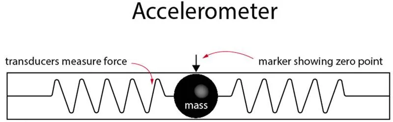
From the above image, we can see the accelerometer contains a known mass, which is attached to a transducer capable of measuring force. However, do note that the mass is constrained within the casing of the accelerometer and can only move left or right—this defines the accelerometer’s measurement axis.
So how does this work in the real world? The image below shows what happens when we place that accelerometer in a car. The car is shown in four states; static, accelerating, cruising at a constant speed and braking. You can see what happens to the mass inside the accelerometer in each scenario.
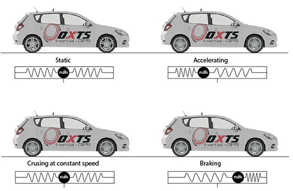
While the car is static and cruising at a constant speed, the mass remains in its centre position as no force is acting on it (at least not along its measurement axis). Because the mass is in its centre position, the transducers detect no force and the accelerometer, therefore, registers no acceleration. When the car accelerates and brakes however the mass moves. While accelerating it moves towards the rear of the sensor, and under braking, it moves towards the front. The harder the car brakes and accelerates, the further the mass is displaced. Whenever the mass is displaced the transducers measuring the force, register a value. Because the sensor knows the mass and the force acting on that mass, it can easily calculate the acceleration that must be causing the mass to move.
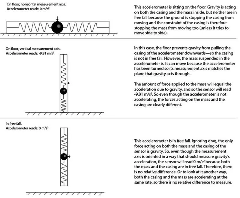
While that seems logical enough, it doesn’t explain why an accelerometer placed vertically on the floor generates a value of 9.81 m/s² even though the floor clearly isn’t moving. And yet an accelerometer in freefall, which clearly is accelerating as it falls through the sky, shows zero acceleration? The answer to that is shown in the image below.
Gyros
Accelerometers are great at measuring straight-line motion, but they’re no good at rotation—that’s where gyros come in. Gyros don’t care about linear motion at all, only rotation. As mentioned earlier, when describing different inertial navigation systems the term gyro can mean different things, depending on what type of system is being described.
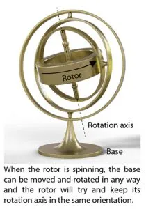
In a traditional sense, a gyroscope employs one or more spinning rotors held in a gimbal or suspended in some other system that is designed to isolate it from external torque. That type of gyroscope works because once the rotor is spinning, it wants to maintain its axis or rotation. In other words, if you projected a line through the spin axis of the gyro, no matter how you try to twist and turn the gyro the projected line would always try to stay pointing towards the same spot. Obviously the gyro could be forced to move if you could apply a torque to it—but that’s what the gimbal is designed to prevent.
A gimbal uses a number of concentric rings mounted inside one another that are connected via orthogonally arranged pivots. This design allows the gyro to freely rotate in three-axes, assuming the rings aren’t in gimbal lock. Gimbal lock occurs when two axes become aligned. In this state, the gimbal has two degrees of freedom instead of three, so it is possible external torque applied in a certain direction might affect the axis of rotation.
Because the gyro’s rotor wants to maintain its initial axis of rotation, sensors can be mounted to the gimbal to measure the relative change in orientation of the external frame to which it is attached. In this way, it’s possible to maintain a picture of how the external frame is orientated relative to the gyro’s axis. The image on the left illustrates this.
The gyros used in strap-down navigators, don’t suffer from gimbal lock. That’s because they’re not gyros in the traditional sense of things. Instead, they are MEMS devices that measure angular velocity—typically in units of °/s (said: degrees per second). So, regardless of the direction, a MEMS gyro is pointing, as long as it’s not rotating about its measurement axis, it will output a value of 0 °/s. If however the gyro was rotating about its measurement axis and taking about one second to perform each revolution, it would output a value of 360 °/s.
This would be positive or negative depending on which direction the rotation was.
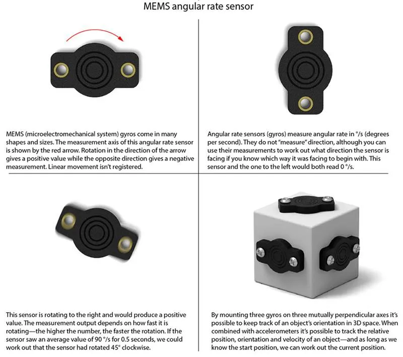
From this you can see that just as with accelerometers, a gyro by itself doesn’t tell the INS which way it is orientated. When it’s first powered up, all the gyro knows is how fast it’s rotating. It is the job of the INS to keep track of all those measurements. So if the INS sees an average velocity of 360 °/s for exactly 0.25 seconds about the z-axis, it knows that regardless of what direction it was pointing to start with, it has now turned through 90° (360 °/s ÷ 0.25 s = 90°). Of course, if the INS knew it was facing north before the movement and it also knows positive gyro values indicate clockwise rotation, then it can easily work out that it is now facing east.
Just as it’s normal to use three accelerometers, it’s normal for the INS to contain three gyros orientated to measure rotation about three mutually perpendicular axes. In this way the INS can measure its orientation in 3D space.
Navigation; putting it all together
Using the measurements taken from the three accelerometers and three gyros, the inertial navigation system keeps track of where it is in three-dimensional space. It does this using a process called dead reckoning. The actual process of dead reckoning is quite easy to understand; you take information from some source (gyros and accelerometers in this case) and turn them into a movement that can be added to your last known position to see where you are now. A simplified 2D example of dead reckoning is shown below.
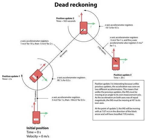
You can see that initially the INS is stationary and aligned squarely to the image, with its x-axis pointing straight up. The image then shows three other positions and the information recorded by the sensors between them. Of course, in reality, the INS would update its position tens or hundreds of times per second, but in this example, position updates are only shown when key changes take place for ease of understanding.
So at time zero, the INS is stationary (and does not know where it is). It then sees an acceleration of 5 m/s² on the x-axis accelerometer for 1 second, which gives it a velocity of 5 m/s (or 18 km/h). It then immediately comes to a complete stop—detecting an acceleration of -10 m/s² for 0.5 seconds. As no other measurements were registered on the other sensors, the strap-down navigator can easily work out that it has moved 3.75 metres in the direction of the x-axis. Again, at this point, the INS doesn’t know where it is as we haven’t given it any position information to begin with.
As soon as the INS stops at position update 1, the z-axis gyro detects a value of 90 °/s for 0.5 seconds; so it knows that it has just turned 45° in a clockwise direction. Again, as soon as that movement is complete the INS again sees acceleration on the x-axis accelerometer. This time it’s 1 m/s² for 10 seconds followed by -5 m/s² for 2 seconds. Using the same techniques as before, the INS can work out that it has now moved 60 metres further on at a 45° angle from where it was at position update 1. This is what was meant earlier on when we talked about the fact that an INS’s position updates were relative to the last known position.
The last movement is different from previous ones. At position update 2, you can see the INS has rotated so it has the same orientation it has initially. When it then moves towards position 3 however, we can that the INS is now moving at an angle to its measurement axis (the IMU frame)—it’s moving backwards and to the right at a bearing of 135°.
Because of this movement, acceleration is registered simultaneously on both the x- and y-axis. There is also no negative acceleration causing the INS to stop—so although the measurements on the accelerometers drop to zero after 1 second, the navigation computer knows that the unit still has a velocity. In this case, it’s moving at 7.07 m/s (about 25 km/h), and position update 3 happens 1.5 seconds after the INS leaves position update 2. In that time the INS has covered 7.95 metres.
Strengths and weaknesses
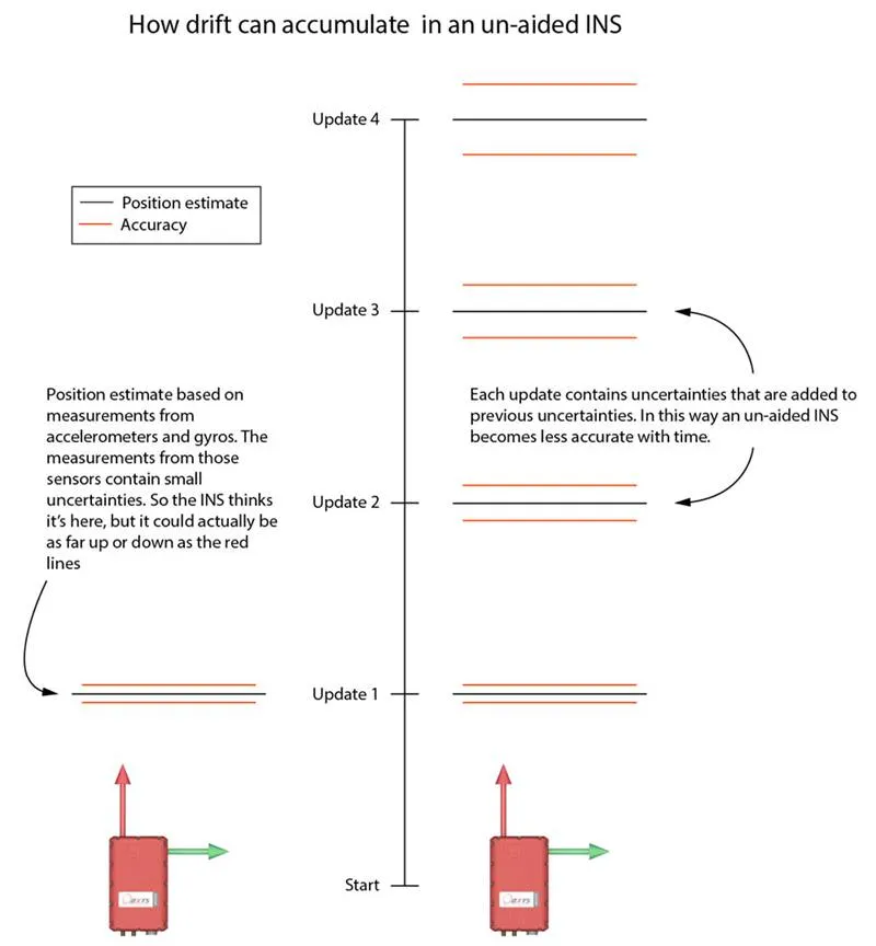
The one thing we haven’t touched upon yet is drift, and this is the Achilles heel of basic un-aided inertial navigation systems—un-aided means systems that only use accelerometer and gyro measurements to calculate their position. Drift is the term used to describe the accumulation of small errors in the accelerometer and gyro measurements, which gradually cause the INS position estimate to become more and more inaccurate.
Understanding why drift occurs is quite easy. Imagine measuring a length of wood with a single 5 m-long tape measure. If you can read the divisions on the tape to an accuracy of 1 mm, then you could easily declare that this piece of wood is 4 m long ± 1 mm. If on the other hand the only tape measure you could find was 0.5 metres long, and you can still only read it to an accuracy of 1 mm, then by the time you have measured and moved along with the tape measure eight times, you would only be able to say that the wood is 4 m long ± 8 mm. In fact, you might not make it 4 m at all.
Drift in the INS accumulates in the same way. Each time an accelerometer or gyro is read, there is a minuscule error in the reading. If we were just taking a single reading to work out how fast we were accelerating or turning, this wouldn’t be a problem. But because the navigation computer is adding up each measurement to work out how it has moved on from the previous position estimate, the minuscule error grows with time.
Of course, this is a very simplified view. A great deal of work has been put into systems that minimise the accumulation of these errors, but there’s no getting away from the fact they are there. That does not, however, mean that the principle of inertial navigation systems is useless—or that it’s inferior to GPS for example. Far from it.
At the beginning of this section we said that drift was the Achilles heel of un-aided inertial navigation systems—so what about aided ones? When you combine an INS with GPS to create a GPS-aided INS (also written as GPS+INS), you solve the problem of drift and also solve the problems that affect GPS too. You can find the section on GPS here…