Omega
Omega was a very long-range Very Low Frequency (VLF) navigation system and the first navigation system providing true global coverage. The system worked by generating hyperbolic lines of position (LOP) by means of phase difference measurements of VLF time-shared transmissions emitted by widely spaced antennae. It was operated by the United States Coast Guard, in partnership with six other nations, from the early 1970's until 1997 when it was decommissioned.
Omega was a worldwide, ground-based radio navigation system, operating in the very low frequency (VLF) band between 10 and 14 kilohertz (kHz). Its purpose was to provide a continuous, medium accuracy aid to navigation which was intended primarily for marine oceanic navigation and for both domestic and oceanic air navigation. The nominal fix accuracy of Omega was two to four nautical miles (nm),
The Omega system consisted of eight widely separated transmitting stations that emitted continuous wave VLF signals. An Omega receiver could determine position from range measurements based on the phase of the received signals from two or more Omega stations, or by phase comparisons between signals of selected pairs of Omega stations, which produced intersecting lines of position (LOP).
The Omega System consisted of three major elements:
· Transmitting System
· Signals in the Earth-Ionosphere Medium
· Receivers and Navigation Computers.
Although each of these major elements could be considered a separate entity, the overall system performance and the ability to navigate with Omega depended upon the performance of each element.
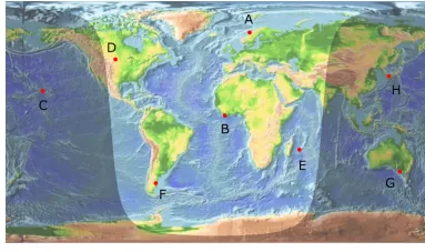
The Transmitting System consisted of a total of eight transmitting stations located around the globe and the procedures required to maintain and synchronize those stations. The eight Omega stations were identified by a letter from A through H and were located as depicted below.
Omega Transmitting Stations Source:WikiCommons
· A: Bratland, Norway
· B: Paynesville, Liberia
· C: Kaneoke, Hawaii, USA
· D: Lamoure, North Dakota, USA
· E: Plaine Chabrier, LaReunion
· F: Golfo Nuevo, Chalut, Argentina
· G: Woodside, Victoria, Australia
· H: Shushi-Wan, Tsushima Island, Japan
The primary components of each transmitting station included the timing equipment required to synchronise their transmission with all of the other stations, a VLF transmitter and the antenna system. By necessity, the antenna required for a VLF signal is very large requiring massive towers or creative use of topographical features. The Omega system made use of three different types of antenna: valley-span, grounded tower, or an insulated tower depending on location.
A synchronization process was required to integrate the otherwise autonomous stations into a system thus making it possible to use the signals to compute a position fix anywhere in the world. In simple terms, an ideal system would derive the signals for each transmitter from a single common frequency source. This would guarantee that each station would transmit its signal at exactly the same time with exactly the same phase. However, the physical separation of the Omega transmitter sites made it unrealistic to use a single frequency source for all eight stations. Instead, the Omega system made use of atomic clocks.
Each Omega station derived its transmitted frequencies from cesium oscillators (commonly referred to as a clock or frequency standard). These devices generate a frequency that is highly stable over long periods of time. On a weekly basis, the system was subject to a synchronization procedure to correct any small shifts in the transmitted signal phase at each station. Consequently, at the receiver, all eight transmitters appeared to be operating from a single frequency source.
All stations transmitted four common frequencies: 10.2 kHz, 11.05 kHz, 11 1/3 kHz, and 13.6 kHz, In addition to these common frequencies, each station also transmitted a unique frequency to allow a receiver to unambiguously identify the station. Transmissions were sequenced in a specified format so that no two stations would transmit on the same frequency at the same time. A continuous wave was transmitted by each station on one of its five frequencies during each transmission segment for 0.9 to 1.2 sec with a 0.2 sec silent interval between segments, The complete format repeated every 10 sec. The sequence of the frequencies transmitted by each station in each of the eight time segments was unique thus providing the receiver with additional information to identify the source of the received signal.
The signal from each of the Omega transmission sites was "launched" by the antenna into the atmosphere between the earth and the lower ionosphere. There it would propagates in all directions for several thousand miles or, under some conditions, completely around the world. Ideally, the signals would travel with uniform intensity and phase in all directions. However, VLF signals are influenced by various physical and electrical factors.
These factors meant that the phase of the Omega signals was not a simple, uniformly increasing function of distance from the transmitter as would be experienced in free space, Therefore, propagation corrections had to be applied to the phase measurements to obtain accurate position fixes. With early receivers, the navigator used propagation correction (PPC) tables to manually correct the fix prior to plotting the information. Later receivers were able to automatically apply the corrections using database information.
The typical Omega user equipment suite consisted of an antenna, receiver, and a navigation computer.
The receiver was used to detect and track the signals from each visible station and measured the phase of the signals relative to a local reference. The number of frequencies simultaneously tracked depended on the particular receiver. The receiver also identified the station that transmitted each of the frequencies in each transmission segment. Station indentification was a necessary component to allow calculation of the range between the receiver and each transmitting station. Since the location (latitude and longitude) of the stations was accurately known, some form of multilateration was used by the navigation computer to determine the latitude and longitude of the receiver.
The signal wavelength of 10.2 kHz, the primary Omega navigation frequency, is about 16 nm. In terms of range from a specific station, each wavelength was referred to as a lane. Within each lane, the signal phase varied from 0 to 360 deg. The Omega receiver was designed to measure the phase of the Omega signal within a given lane. As the range to the transmitter is equal to the number of whole lanes plus the fractional part of the lane indicated by the phase measurement, the receiver must "know" or keep track of the number of whole lanes. This was normally achieved by accurately initialising the position of the receiver at the point of departure.
The navigation computer could determine position in one of two ways, by direct ranging or by hyperbolic (range difference) calculations. Direct ranging involved making distance calculations to two or more stations and then plotting intersecting arcs on a chart to determine position. Digital computers could "plot" these arcs electronically and display the position as a latitude and longitude. In hyperbolic mode, the calculations were based on the difference in signal phase between pairs of transmitters which produced hyperbolic lines of position. In the early days of Omega, paper charts with precalculated LOPs depicted were used to plot position. Well before the decommissioning of the Omega system in 1997, advances in digital navigation computers had automated the fix determination process and the processor used all available transmitted signals to maximise the accuracy of the displayed position.