Decca Navigator System
The Decca Navigator System was a hyperbolic radio navigation system which allowed ships and aircraft to determine their position by receiving radio signals from fixed navigational beacons. The system used phase comparison of two low frequency signals between 70 and 129 kHz, as opposed to pulse timing systems like Gee and LORAN. This made it much easier to implement the receivers using 1940s electronics, eliminating the need for a cathode ray tube.
The system was invented in the US, but development was carried out by Decca in the UK. It was first deployed by the Royal Navy during World War II when the Allied forces needed a system which could be used to achieve accurate landings and was not known to the Germans and thus free of jamming. After the war, it was extensively developed around the UK and later used in many areas around the world. Decca's primary use was for ship navigation in coastal waters, offering much better accuracy than the competing LORAN system. Fishing vessels were major post-war users, but it was also used on aircraft, including a very early (1949) application of moving map displays. The system was deployed extensively in the North Sea and was used by helicopters operating to oil platforms.
The opening of the more accurate Loran-C system to civilian use in 1974 offered stiff competition, but Decca was well established by this time and continued operations into the 1990s. Decca was eventually replaced, along with Loran and similar systems, by the GPS during the 1990s. The Decca system in Europe was shut down in the spring of 2000, and the last worldwide chain, in Japan, in 2001.

The display head, or "decometer bowl", of a Decca Navigator Mk 12 (ca. 1962). Not shown is the much larger receiver unit.
Principles of Operation
Overview
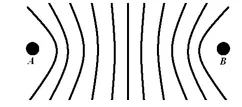
The Decca Navigator principle.
The phase difference between the signals received from stations A (Master) and B (Slave) is constant along each hyperbolic curve. The foci of the hyperbola are at the transmitting stations, A and B.
The Decca Navigator System consisted of a number of land-based radio beacons organised into chains. Each chain consisted of a master station and three (occasionally two) secondary stations, termed Red, Green and Purple. Ideally, the secondaries would be positioned at the vertices of an equilateral triangle with the master at the centre. The baseline length, that is, the master-secondary distance, was typically 60–120 nautical miles (110–220 km).
Each station transmitted a continuous wave signal that, by comparing the phase difference of the signals from the master and one of the secondaries, resulted in a set of hyperbolic lines of position called a pattern. As there were three secondaries there were three patterns, termed Red, Green and Purple. The patterns were drawn on nautical charts as a set of hyperbolic lines in the appropriate colour. Receivers identified which hyperbola they were on and a position could be plotted at the intersection of the hyperbola from different patterns, usually by using the pair with the angle of cut closest to orthogonal as possible.
Detailed Principles of Operation
When two stations transmit at the phase-locked frequency, the difference in phase between the two signals is constant along a hyperbolic path. Of course, if two stations transmit on the same frequency, it is practically impossible for the receiver to separate them; so instead of all stations transmitting at the same frequency, each chain was allocated a nominal frequency, 1f, and each station in the chain transmitted at a harmonic of this base frequency, as follows:
Station | Harmonic | Frequency (kHz) |
Master | 6f | 85.000 |
Purple | 5f | 70.833 |
Red | 8f | 113.333 |
Green | 9f | 127.500 |
The frequencies given are those for Chain 5B, known as the English Chain, but all chains used similar frequencies between 70 kHz and 129 kHz.
Decca receivers multiplied the signals received from the Master and each Slave by different values to arrive at a common frequency (least common multiple, LCM) for each Master/Slave pair, as follows:
Pattern | Slave Harmonic | Slave Multiplier | Master Harmonic | Master Multiplier | Common Frequency |
Purple | 5f | ×6 | 6f | ×5 | 30f |
Red | 8f | ×3 | 6f | ×4 | 24f |
Green | 9f | ×2 | 6f | ×3 | 18f |
It was phase comparison at this common frequency that resulted in the hyperbolic lines of position. The interval between two adjacent hyperbolas on which the signals are in phase was called a lane. Since the wavelength of the common frequency was small compared with the distance between the Master and Slave stations there were many possible lines of position for a given phase difference, and so a unique position could not be arrived at by this method.
Other receivers, typically for aeronautical applications, divided the transmitted frequencies down to the basic frequency (1f) for phase comparison, rather than multiplying them up to the LCM frequency.
Lanes and Zones
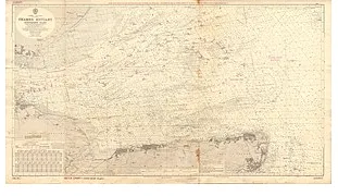
A 1967 Admiralty Decca Chart of the Thames Estuary, marked with red and green lanes and zones.
Early Decca receivers were fitted with three rotating Decometers that indicated the phase difference for each pattern. Each Decometer drove a second indicator that counted the number of lanes traversed – each 360 degrees of phase difference was one lane traversed. In this way, assuming the point of departure was known, a more or less distinct location could be identified.
The lanes were grouped into zones, with 18 green, 24 red, or 30 purple lanes in each zone. This meant that on the baseline (the straight line between the Master and its Slave) the zone width was the same for all three patterns of a given chain. Typical lane and zone widths on the baseline are shown in the table below (for chain 5B):
Lane or Zone | Width on Baseline |
Purple lane | 352.1 m |
Red lane | 440.1 m |
Green lane | 586.8 m |
Zones (all patterns) | 10563 m |
The lanes were numbered 0 to 23 for red, 30 to 47 for green and 50 to 79 for purple. The zones were labelled A to J, repeating after J. A Decca position coordinate could thus be written: Red I 16.30; Green D 35.80. Later receivers incorporated a microprocessor and displayed a position in latitude and longitude.
Multipulse
Multipulse provided an automatic method of lane and zone identification by using the same phase comparison techniques described above on lower frequency signals.
The nominally continuous wave transmissions were in fact divided into a 20-second cycle, with each station in turn simultaneously transmitting all four Decca frequencies (5f, 6f, 8f and 9f) in a phase-coherent relationship for a brief period of 0.45 seconds each cycle. This transmission, known as Multipulse, allowed the receiver to extract the 1f frequency and so to identify which lane the receiver was in (to a resolution of a zone).
As well as transmitting the Decca frequencies of 5f, 6f, 8f and 9f, an 8.2f signal, known as Orange, was also transmitted. The beat frequency between the 8.0f (Red) and 8.2f (Orange) signals allowed a 0.2f signal to be derived and so resulted in a hyperbolic pattern in which one cycle (360°) of phase difference equates to 5 zones.
Assuming that one’s position was known to this accuracy, this gave an effectively unique position.
Range and Accuracy
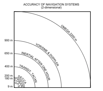
During daylight, ranges of around 400 nautical miles (740 km) could be obtained, reducing at night to 200 to 250 nautical miles (460 km), depending on propagation conditions.
The accuracy depended on:
· Width of the lanes
· Angle of cut of the hyperbolic lines of position
· Instrumental errors
· Propagation errors (for example, Skywave)
By day these errors could range from a few meters on the baseline up to a nautical mile at the edge of coverage. At night, skywave errors were greater and, on receivers without multipulse capabilities, it was not unusual for the position to jump a lane, sometimes without the navigator knowing.
Although in the days of differential GPS this range and accuracy may appear poor, in its day the Decca system was one of the few, if not the only, position fixing system available to many mariners. Since the need for an accurate position is less when the vessel is further from land, the reduced accuracy at long ranges was not a great problem.